Model trains have always had a charming way of making adults suddenly care very deeply about ballast color, tunnel portals, and whether a locomotive sounds “right” while crawling past a station the size of a sandwich crumb. But as model railroads shrink into extremely small scales, especially T Gauge, the old mechanical formula starts to show its limits. Tiny wheels, tiny motors, tiny gears, and tiny electrical contacts can turn a relaxing hobby into a surprisingly dramatic negotiation with physics.
That is where PCB linear motors for model trains become fascinating. Instead of packing a motor, gears, pickups, and wiring into a miniature locomotive, the propulsion system can be moved into the track itself. A printed circuit board becomes the motor. The train becomes a lightweight vehicle carrying magnets. The result is not just a clever engineering trick; it is a completely different way to think about miniature railway animation.
In simple terms, a PCB linear motor uses copper coil patterns printed on a circuit board to create a moving magnetic field. Magnets mounted under the train respond to that field, pulling or pushing the vehicle along the route. It is the “unrolled motor” idea: instead of spinning a rotor inside a round motor case, the motor is stretched out into a line or path. For tiny model trains, this can solve several problems at once, including poor wheel pickup, unreliable micro gearboxes, and limited space inside the locomotive shell.
What Is a PCB Linear Motor?
A linear motor is an electric motor designed to produce motion in a straight or guided path rather than rotary motion. In a conventional motor, coils and magnets create torque around a shaft. In a linear motor, the same electromagnetic relationship is arranged along a track, so the useful output is thrust. For model trains, that thrust can move a vehicle down a scenic route without a spinning motor onboard.
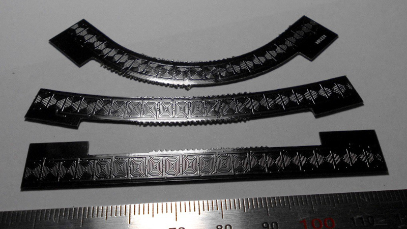
A PCB linear motor takes the concept one step further by making the motor coils directly on a printed circuit board. Instead of winding copper wire around a bobbin, the designer lays out flat spiral coils as copper traces. These coils are then energized in a controlled sequence. When paired with small permanent magnets under a train, the board can create repeatable motion.
The appeal is obvious: PCBs are flat, repeatable, and relatively affordable to manufacture. If a track section can be designed as a circuit board, it can include coils, sensors, solder pads, connectors, LED pads, control electronics, and mounting holes all in one tidy package. It is model railroading with a little bit of robotics hiding under the scenery.
Why Model Trains Need a Different Propulsion Idea
Traditional model trains usually rely on powered rails. Electricity flows through the rails, into the wheels, through pickups, and finally into a tiny motor inside the locomotive. This works beautifully in larger scales such as HO, O, or even N scale. But when the scale becomes extremely small, every weakness becomes louder than a steam whistle in a library.
Dirt, oxidation, uneven track, light vehicle weight, and imperfect wheel contact can interrupt power. The smaller the train, the less mass it has to press the wheels onto the rails. The smaller the mechanism, the more difficult it becomes to build reliable gears, axles, and pickups. Even a speck of dust can behave like a boulder with delusions of grandeur.
T Gauge is a perfect example. With a scale around 1:450 and a 3 mm track gauge, it allows entire railway scenes to fit into spaces where larger scales would barely fit a station platform. But that miniature magic comes with mechanical compromises. PCB linear motors offer a way to remove the most troublesome moving parts from the train itself.
How PCB Linear Motors Work in Model Train Layouts
In a PCB linear motor layout, the track is not just a passive path. It is an active electromagnetic system. The board contains repeated coil patterns, often arranged in multiple phases. A controller energizes these phases in sequence, producing a traveling magnetic field. Vehicles carry small neodymium magnets underneath. As the energized coils shift, the magnets follow.
The Three-Phase Coil Track
A common approach is a three-phase synchronous linear motor. Think of it like a stepper motor that has been flattened and stretched into track form. The board may contain three interleaved sets of coils. By energizing phase A, then phase B, then phase C, and repeating that pattern, the system creates controlled movement along the track.
Microstepping makes the motion smoother. Instead of abruptly switching from one coil group to the next, the controller can blend current between phases. This reduces jerky movement and helps the train glide in a more realistic way. For tiny layouts, smooth low-speed operation is a big win. Nothing ruins the illusion faster than a miniature commuter train hopping along like it just drank six espressos.
The Magnet Vehicle
The train body can be extremely simple. It may not need a motor, gearbox, electrical pickup, decoder, or powered wheels. It only needs magnets placed correctly underneath. Neodymium magnets are popular because they provide strong magnetic fields in very small sizes. For ultra-small scales, that compact strength matters.
The vehicle can be a lightweight printed shell, a tiny plastic body, or a detailed model with a smooth underside. The magnets interact with the PCB coil field below. Because propulsion comes from the track, the train can be lighter and mechanically simpler than a conventional powered model.
Key Advantages of PCB Linear Motors For Model Trains
1. Fewer Mechanical Parts
Tiny gear trains are impressive, but they are also fragile. A PCB linear motor removes the need for onboard gears and motors in the smallest vehicles. That means fewer parts to wear out, jam, bind, or disappear forever into the carpet dimension.
2. No Rail Pickup Problems
Traditional model locomotives often depend on clean electrical contact between wheel and rail. PCB linear propulsion can avoid that dependency. The train can move because of magnetic interaction with the powered board, not because its wheels are collecting current. This is especially valuable in small scales, where light vehicles and microscopic contact areas can cause stalling.
3. Smooth Low-Speed Motion
When the coils are controlled carefully, PCB linear motors can produce slow, smooth, repeatable movement. That opens the door to realistic station stops, shuttle operation, street trams, mine carts, industrial scenes, and hidden animation effects.
4. Thin Track Construction
Since the motor is built into a circuit board, the track can remain very flat. This is useful for compact layouts, display dioramas, museum exhibits, desktop scenes, and portable modules. The PCB can be hidden under printed road surfaces, scenic paving, or custom artwork.
5. Repeatable Manufacturing
Once a PCB track section is designed and tested, it can be reproduced consistently. That is a major benefit over hand-wound experimental coil assemblies. PCB fabrication makes it possible to create curves, sidings, display loops, and modular route sections with consistent coil geometry.
The Design Challenges Nobody Should Ignore
PCB linear motors are clever, but they are not magic. They still obey electrical, magnetic, thermal, and mechanical rules. The first challenge is current. Copper PCB traces have resistance, and resistance creates heat. A motor coil that looks beautiful in design software can become a tiny toaster if the trace width, copper thickness, duty cycle, and cooling are not planned correctly.
Designers should use PCB trace-current guidance such as IPC-2152 principles when estimating safe current capacity. Wider traces, heavier copper, copper pours, thermal vias, and thoughtful layer stacking can all help manage temperature. For hobby prototypes, short test runs may seem fine, but continuous operation on a display layout is a different situation.
Another challenge is magnetic alignment. The spacing between coils and magnets affects thrust. Too much air gap weakens the force. Too little clearance can cause dragging. Magnet polarity must also be consistent. If one magnet is flipped the wrong way, the train may behave like it has suddenly remembered an urgent appointment in the opposite direction.
Curves also require careful planning. A straight linear motor is easier to design than a curved route. Model railways, however, love curves. A PCB coil pattern must follow the intended path smoothly enough that the magnet vehicle remains stable. Track joints must also be handled cleanly so the magnetic field does not create a dead spot or sudden lurch.
Electronics and Control Options
A PCB linear motor needs a controller capable of energizing coil phases in sequence. Depending on the design, this may involve half-bridge drivers, three-phase motor drivers, MOSFET arrays, current sensing, and a microcontroller. A simple demonstration can use open-loop stepping, while a more advanced layout might use sensors for position feedback.
Open-loop control is easier: the controller assumes the train follows the moving magnetic field. This can work well if the vehicle is light, the magnets are strong, the track is clean, and the acceleration is gentle. Closed-loop control is more advanced: sensors detect where the train actually is, and the controller adjusts accordingly.
Possible sensors include Hall-effect sensors, optical interrupters, reed switches, or even camera-based tracking for experimental setups. For web-published hobby builds, the best advice is to start simple. Build a short straight test track first. Make one vehicle move reliably. Then think about curves, stations, automation, and scenic details.
PCB Layout Considerations
The PCB is the heart of the system, so layout quality matters. Coil shape determines magnetic performance. Trace width determines resistance and heat. Layer alignment affects thrust and smoothness. Solder mask thickness, surface material, and any printed scenic overlay can influence the air gap between coils and magnets.
A double-sided PCB can increase coil density or improve phase spacing. Some designs place coil patterns on both sides of the board to achieve finer effective pitch. Smaller pitch can mean smoother motion, but it also increases layout complexity. The board may need careful routing to avoid trace crowding, current bottlenecks, and inconsistent coil resistance.
Designers should also consider connectors. A beautiful track section is much less fun if every wire must be soldered directly to fragile pads under the layout. Modular connectors, test pads, labeled phases, and mounting holes make debugging easier. Future-you will be grateful. Future-you is already tired.
Best Uses for PCB Linear Motor Model Train Layouts
PCB linear motors are especially attractive for very small scales, novelty layouts, display pieces, and automated scenes. They are not necessarily a replacement for every traditional model railroad. A large HO freight layout with long consists, DCC sound, and complex switching may still be better served by conventional locomotives. But for ultra-small trains and animated dioramas, PCB propulsion is a serious idea.
Micro Layouts
T Gauge and other extremely small formats can benefit from track-based propulsion because the vehicle has so little internal space. A PCB linear motor can turn a tiny loop, shuttle, or scenic branch line into a reliable moving display.
Museum and Retail Displays
Displays often need repeatable motion for long periods. Removing onboard mechanisms can reduce maintenance. The track can be controlled from hidden electronics, while the visible train remains simple and lightweight.
Animated Scenery
The same technology can move more than trains. Cars, boats, factory carts, airport service vehicles, amusement park rides, and mining equipment can all be animated with magnet-carrying vehicles over PCB coil paths.
Specific Example: A Tiny Station Shuttle
Imagine a coffee-table layout with a T Gauge station, a short platform, a tunnel entrance, and a train that shuttles back and forth every few minutes. With conventional power, the tiny train needs rail pickup, a motor, a drivetrain, and reliable reversing electronics. With a PCB linear motor, the route can be built as a powered board under the track surface. The train carries magnets. The controller accelerates it gently from the tunnel, slows it into the station, pauses, and then returns.
Add LEDs in the station, a sound module under the base, and a printed city backdrop, and suddenly the layout feels alive. The train does not need to pull power from the rails. It does not need to haul a motor. It does not care if the visible rails are decorative. That is the real creative power of PCB linear motors for model trains: they separate visual realism from mechanical burden.
Practical Building Tips
Start with a straight test section before designing an entire railway empire. Use a simple magnet carrier so you can quickly test spacing, polarity, and current levels. Measure coil resistance and board temperature. Test different magnet sizes and heights. Keep the first goal modest: smooth motion over a few inches.
Once the basic movement works, experiment with acceleration curves. Sudden starts can cause the magnet vehicle to lose synchronization. Gradual ramping helps the train follow the field. If the vehicle slips, reduce speed, increase magnet strength, improve alignment, or adjust the phase timing.
For scenery, avoid thick materials between the PCB and magnets. A thin printed overlay may work well, while thick plastic roadbed may reduce magnetic force too much. If appearance matters, test the final scenic layer early rather than after everything is glued down with heroic confidence.
Experience Notes: What It Feels Like to Work With PCB Linear Motors For Model Trains
Building with PCB linear motors feels different from ordinary model railroading. With a conventional train, your attention usually goes to wheels, couplers, track gauge, rail joiners, decoders, and cleaning. With PCB propulsion, your mindset shifts toward magnetic fields, coil timing, board heat, phase order, and vehicle balance. It is still a train hobby, but now it is wearing an electrical engineering hat and pretending that is perfectly normal.
One of the first experiences a builder may notice is how sensitive the system is to spacing. A magnet that seems strong in your hand can feel much less powerful once it is several millimeters above a PCB coil. The air gap matters. The thickness of solder mask, paper artwork, adhesive, roadbed, and vehicle clearance all add up. A small change can turn confident motion into weak twitching. The best approach is to test with temporary spacers before committing to a final mechanical design.
Another important lesson is that heat deserves respect. Because the coils are copper traces, they can warm up when current flows for long periods. A short demo may run beautifully, but a display that operates all afternoon needs safer margins. It helps to use current limiting, avoid unnecessary stall conditions, and design the board with enough copper area. A thermal camera is wonderful if available, but even careful finger testing during early low-power experiments can reveal obvious hot spots. Naturally, do not touch powered circuits blindly; the goal is curiosity, not barbecue.
Tuning motion is also surprisingly satisfying. When the phase sequence is wrong, the vehicle may buzz, hesitate, or move backward. When the timing improves, it begins to glide. Add microstepping or smoother current control, and the train starts to look less like a lab experiment and more like a miniature transit system. That moment is addictive. It is the same joy as seeing a traditional locomotive run after repairs, except this time the “locomotive” may just be a tiny shell with magnets under it.
The most practical experience is to keep the vehicle simple during early testing. Do not begin with a perfectly painted passenger train that took six evenings and one emotional support beverage to finish. Start with a plain slider, a small printed body, or a scrap carrier. Mark magnet polarity clearly. Make notes about magnet spacing, coil current, board temperature, and speed. The data may look boring, but it prevents the classic hobby tragedy of changing five things at once and then having no idea which one fixed the problem.
Finally, PCB linear motors encourage creative layout design. Since the visible rails do not have to supply power, the “track” can be disguised as pavement, factory floor, monorail guideway, embedded tram line, or futuristic maglev route. For modelers who enjoy compact scenes, this is liberating. The technology is not perfect, and it will not replace every conventional locomotive, but it opens a wonderful new category: tiny trains that move because the layout itself is alive underneath them.
Conclusion
PCB linear motors for model trains combine printed circuit board design, magnetic propulsion, and miniature railway creativity into one wonderfully nerdy package. They are especially promising for tiny scales where traditional motors, pickups, and gears become difficult to manage. By moving the motor into the track and placing magnets under the vehicle, builders can create smooth, reliable, and visually flexible motion.
The technology does require careful design. Coil geometry, current capacity, thermal management, magnet spacing, control electronics, and route shape all matter. But for hobbyists willing to experiment, the reward is huge: ultra-small trains that glide through scenes without relying on fragile onboard mechanisms. It is model railroading, electronics prototyping, and a little bit of magnetic wizardry rolled into one. And honestly, if your train layout can make visitors ask, “Wait, how is that moving?” you have already won the day.