A saw blade is supposed to be the disciplined one in the shop. You mark the line, start the cut, guide the material, and expect the blade to behave like a tiny steel soldier. Then reality enters wearing safety glasses: the blade flexes, twists, wanders, complains silently, and sometimes takes your carefully planned cut on a scenic detour.
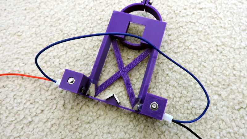
That is what makes the idea behind an optical sensor that keeps an eye on a wandering saw blade so fascinating. Instead of treating blade drift as a mysterious shop gremlin, the system watches the blade in real time, measures its position, and turns visual movement into useful data. In the case that inspired this topic, maker Andrew Consroe used a Raspberry Pi HQ Camera, mirrors, a 3D-printed frame, and clever computer vision to track a thin scroll saw blade without touching it. The result is a “Split Vision Periscope” concept capable of measuring blade position in two dimensions with impressive precision.
For woodworkers, makers, CNC experimenters, and anyone who has ever blamed a bad cut on “the wood having opinions,” this is more than a neat gadget. It is a window into the future of smarter saws, non-contact sensing, optical measurement, and machine-assisted accuracy in the workshop.
What Does “Wandering Saw Blade” Actually Mean?
A wandering saw blade is a blade that does not stay where the operator or machine expects it to be. In bandsaws, this is often called blade drift, where the cut moves left or right even when the workpiece is fed straight. In scroll saws, especially ultra-thin blades, wandering can show up as flexing, twisting, lagging behind the intended path, or deflecting under cutting pressure.
The annoying part is that blade movement is rarely caused by one villain. It is usually a committee meeting of small problems: blade tension, feed rate, tooth geometry, material density, guide alignment, dull teeth, vibration, and heat. A sharp blade with correct tension may behave beautifully in soft pine, then suddenly develop a personality disorder when it hits a knot, resin pocket, dense hardwood grain, or a slightly aggressive feed rate.
Why Thin Blades Are Especially Tricky
Scroll saw blades and narrow bandsaw blades are designed to make tight curves and detailed cuts. That flexibility is a feature, not a buguntil you need absolute positional accuracy. A thin blade can bend sideways before it visibly fails. In manual work, the operator compensates by feel. In a CNC scroll saw or automated cutting system, however, the machine needs numbers. It cannot “feel” blade lag unless a sensor tells it what is happening.
That is where an optical saw blade sensor becomes valuable. It gives the system eyes.
How an Optical Sensor Watches a Saw Blade Without Touching It
An optical sensor measures something using light. Depending on the design, it may detect interruption of a beam, reflection from a surface, contrast changes, edges in a camera image, or the position of a laser line. In industrial settings, photoelectric sensors and machine vision systems are already used to detect objects, measure dimensions, inspect products, and guide automation.
For a moving saw blade, contact measurement is awkward. Anything that touches the blade risks wear, heat, vibration, friction, inaccurate readings, and possibly a very bad afternoon. A non-contact optical system avoids those problems. It can observe the blade from a safe distance, gather position data, and leave the cutting action alone.
The Split Vision Periscope Idea
The clever part of the Split Vision Periscope approach is that one camera can see the blade from two perspectives. Mirrors redirect the view so the camera receives two images of the same blade from different angles. With the blade shown against a dark background, computer vision software can identify its edges and estimate its position in two axes.
Think of it like giving the camera a pair of tiny mechanical side-eyes. Instead of asking, “Where does the blade appear from one direction?” the system asks, “Where is the blade in space when viewed from two directions?” That makes it possible to detect both lateral movement and twisting behavior, which matters because a saw blade does not always drift politely in one dimension.
Why the Raspberry Pi HQ Camera Makes Sense
The Raspberry Pi HQ Camera is popular with makers because it combines a high-resolution image sensor with interchangeable lens support. For a project like saw blade tracking, resolution matters because the blade movement may be tiny. Lens choice matters because the field of view, working distance, focus, and distortion can affect measurement accuracy.
A typical workshop camera watching a whole table may be fine for recording a project video, but measuring blade movement is a different beast. The camera needs controlled lighting, a stable mount, a sharply focused view, and enough contrast to separate the blade from the background. Otherwise, the computer vision algorithm is not tracking a blade; it is staring into a gray soup and making optimistic guesses.
Why Computer Vision Is the Secret Sauce
Computer vision turns images into measurements. A camera by itself simply captures pixels. Software gives those pixels meaning. In a saw blade monitoring system, the software may crop the image to a region of interest, convert it to grayscale, threshold the blade against the background, find edges or contours, and calculate the blade’s centerline.
This is the same general logic used in many industrial machine vision systems: control the lighting, simplify the background, capture a reliable image, extract the important feature, and convert that feature into a decision or measurement. The glamorous part is the algorithm. The unglamorous part is making sure dust, glare, vibration, and bad lighting do not bully the algorithm into nonsense.
Lighting Is Not Optional
Good machine vision begins with good lighting. If the blade is shiny, it may reflect random highlights. If the background is messy, the software may confuse sawdust or scratches for blade edges. If the light changes during operation, the measurement may shift even when the blade does not.
That is why the optical layout matters. A black background, consistent illumination, and controlled camera angle can make the blade stand out clearly. The goal is to make the software’s job boring. In machine vision, boring is excellent. Exciting images usually mean debugging at 1:00 a.m. while muttering at a histogram.
Common Causes of Saw Blade Drift and Deflection
An optical sensor can reveal blade movement, but it does not magically remove the mechanical causes. To understand why the data matters, it helps to look at what makes blades wander in the first place.
1. Blade Tension
Insufficient blade tension allows a blade to flex too easily. On a bandsaw, low tension can lead to flutter, rough cuts, and drift. On a scroll saw, a blade that is not tensioned correctly may lag behind the programmed path. Too much tension is not ideal either because it can stress the blade, the machine, or the tensioning system.
2. Feed Rate
Push too hard and the blade bends before it cuts. This is especially noticeable when cutting thick stock or dense material. In CNC work, feed rate must match the blade, material, and cut geometry. The machine may be perfectly following the toolpath while the blade tip quietly takes a different route.
3. Tooth Sharpness and Geometry
A dull blade rubs instead of slicing. That creates heat, extra force, and sideways pressure. Tooth set can also influence how a blade tracks through material. If the teeth cut more aggressively on one side, the blade may favor that direction like a shopping cart with one bad wheel.
4. Blade Guides and Wheel Tracking
Guides support the blade near the work and limit twisting. If they are set too far away, misaligned, dirty, or worn, the blade gets more room to misbehave. On bandsaws, wheel tracking and guide setup also affect how predictably the blade enters the cut.
5. Material Variation
Wood is not uniform. Grain direction, knots, moisture, glue lines, and density changes all affect cutting forces. Plastics, foam, composites, and thin plywood introduce their own surprises. A sensor is useful because it can show how the blade reacts to real material, not just the ideal conditions imagined in the CAD file.
From Measurement to Smarter Control
The most exciting possibility is not just watching the bladeit is using the measurement to improve the cut. Once the system knows where the blade actually is, it can compare that position with where the blade should be. That difference becomes an error signal.
In a basic setup, the sensor might simply log blade movement so the maker can diagnose problems. In a more advanced system, the CNC controller could slow the feed rate when deflection increases, adjust the toolpath to compensate, pause before a fragile turn, or warn the operator that the blade is losing accuracy.
Closed-Loop Cutting
Traditional CNC cutting often assumes the tool behaves like a rigid object. A router bit comes close to that assumption. A scroll saw blade does not. Closed-loop blade tracking would allow the machine to respond to the real blade position, not just the commanded position.
Imagine cutting a jigsaw puzzle, intricate inlay, or delicate model part. The machine sees the blade flexing slightly behind the path and automatically reduces feed speed. It notices twist during a tight curve and changes how it approaches the corner. It detects abnormal vibration and stops before the blade breaks. That is not science fiction; it is the logical next step when machine vision meets motion control.
Potential Applications Beyond a CNC Scroll Saw
The same concept could apply to many cutting environments where blade position matters. In sawmills, blade drift can waste material and reduce yield. In thin-cutting bandsaws, small deviations can affect veneer, lamella, flooring blanks, and precision wood components. In metalworking, blade deviation can ruin expensive stock or shorten blade life. In composite cutting, deflection may affect edge quality and dimensional accuracy.
Industrial saw blade monitoring systems already use sensors to detect drift, force, guide pressure, or spacing. A maker-built optical sensor sits in the same family of ideas, but with a wonderfully accessible flavor: camera, mirrors, 3D printing, software, and enough stubbornness to make a blade confess where it really went.
Design Challenges: Dust, Vibration, and Reality
Every beautiful optical system eventually meets sawdust. Dust can settle on mirrors, lenses, lights, and backgrounds. Vibration can shift calibration. Heat can change dimensions slightly. A shiny blade can produce reflections that look different as it twists. These challenges do not make the idea impractical, but they do mean the design must be rugged.
Keeping the Optics Clean
Dust control could include air assist, sealed optical paths, replaceable protective windows, positive-pressure enclosures, or careful placement below the work surface. The original periscope-style arrangement is smart because it keeps the camera and lens away from the most violent part of the cutting zone. Still, mirrors and windows need protection because sawdust is nature’s glitter, except less festive and more abrasive.
Calibration Matters
For accurate measurement, the system must know how pixels relate to real-world distance. Calibration may involve a known reference object, a fixed blade position, or a test pattern. If the mirror geometry changes, the camera mount shifts, or the focus moves, the calibration may need to be checked again.
Latency and Processing Speed
A camera-based sensor must capture images, process them, and deliver results quickly enough to be useful. If the saw blade moves faster than the system can measure and respond, the data becomes old news. Reducing the region of interest, simplifying the image, improving lighting, and using efficient edge detection can help. For some applications, a simpler optical sensor or photodiode arrangement may be faster, but a camera gives richer information.
Safety: A Sensor Is Not a Substitute for Guards
An optical blade sensor can improve measurement and possibly reduce waste, but it is not a safety shield. Saws still need proper guards, guide adjustment, blade tension, dust collection, and safe operating practices. Operators should keep hands out of the cut line, use push sticks when appropriate, disconnect power before adjustments, and follow the manufacturer’s instructions.
In other words, do not install a camera and suddenly treat your saw like a friendly kitchen appliance. It is still a fast-moving blade. The sensor is there to measure behavior, not negotiate with physics on your behalf.
Why This Project Matters to Makers
The beauty of the optical saw blade sensor is that it shows how accessible high-precision measurement has become. A decade ago, a hobbyist might have needed expensive industrial hardware to attempt this kind of monitoring. Today, a maker can combine a Raspberry Pi camera, 3D-printed parts, open-source computer vision tools, and clever optics to solve a real mechanical problem.
It is also a reminder that great engineering often begins with admitting the machine is not doing what the plan says. Instead of pretending the blade is rigid, the sensor accepts reality: the blade flexes. Then it measures that reality. That humble step is what turns guessing into engineering.
Practical Lessons for Building Your Own Optical Blade Sensor
If you want to experiment with a similar system, start simple. Do not begin by building a fully closed-loop CNC controller unless your favorite hobby is inventing new swear words. First, mount a camera securely and capture clear images of the blade. Then improve the background and lighting. Next, write or adapt software that detects the blade edge reliably. After that, calibrate pixel movement into real measurements.
Use Contrast Before Complexity
A clean black background behind a bright blade may outperform a complicated algorithm. Before adding artificial intelligence, ask whether a better light, better angle, or better background would solve the problem. Most machine vision projects improve dramatically when the scene is physically simplified.
Measure Before You Control
Logging blade movement is useful by itself. You can compare different blades, materials, feed rates, and tensions. You may discover that a blade only wanders during tight turns, or only after warming up, or only when cutting a specific material. Those findings can improve your process even before automation enters the picture.
Make the System Serviceable
Anything mounted near a saw should be easy to clean, inspect, and replace. Use protective covers, removable windows, and sturdy mounts. If a mirror needs cleaning, you should not have to dismantle half the machine and question your life choices.
Experience Notes: What Working Around Wandering Blades Teaches You
Anyone who has spent time with scroll saws, bandsaws, or small CNC machines learns a humbling truth: the blade always gets a vote. You can draw the perfect vector path, square the fence, tension the blade, and prepare the stock like a responsible adult. Then the first cut begins, the blade meets a denser patch of material, and suddenly the line is not quite where the drawing promised it would be.
One of the most useful habits is to treat blade drift as feedback rather than failure. If the blade consistently leans away from the cut, something is being overloaded. The feed rate may be too high. The blade may be too narrow for the material thickness. The teeth may be dull. The guides may be too far above the work. In a manual shop, you learn to hear and feel these problems. The sound changes. The cut heats up. The material begins to resist. The blade appears to hesitate before a curve. That is the saw whispering, “Please stop making me do gymnastics.”
An optical sensor adds a new kind of experience: visual proof. Instead of relying only on the finished cut, you can see what the blade did during the cut. That is powerful because the finished part often hides the cause. A bad edge might come from feed pressure, vibration, dull teeth, or blade twist. A live measurement gives you a timeline. You can see when deflection starts, how large it becomes, and whether it recovers after the cut exits a difficult section.
In practical use, the first surprise would probably be how much movement happens before the human eye notices. Thin blades can flex by tiny amounts that still matter for fine work. A puzzle piece, model rib, decorative inlay, or tight internal curve may not tolerate much error. The second surprise would be how strongly technique affects measurement. Slow down slightly, and the blade may straighten. Lower the guide post, and twist may shrink. Swap to a sharper blade, and the sensor trace may suddenly look calm.
Another lesson is that optical sensing rewards cleanliness and consistency. A dusty lens or flickering light can ruin otherwise good data. Shops are not laboratories, so the sensor must be designed with the mess in mind. Airflow, dust collection, sealed optics, and simple calibration routines matter just as much as code. The best algorithm cannot rescue an image that looks like it was filmed through a powdered doughnut.
For CNC builders, the experience is even more interesting. A machine can follow coordinates perfectly while the blade does not. That difference explains why some cuts look inaccurate even when the motors, belts, and rails are behaving. A blade is not a router bit. It is a flexible cutting element under load. Once you accept that, the design philosophy changes. You stop asking only, “Where did I command the tool to go?” and start asking, “Where is the cutting edge right now?”
The biggest takeaway is patience. An optical saw blade sensor is not just a gadget; it is a diagnostic teacher. It can show that a slower feed produces cleaner geometry, that better lighting produces better measurements, and that mechanical stiffness still matters. It also reminds us that precision is rarely one magic upgrade. It is a stack of small improvements: sharp blade, stable frame, controlled feed, good guides, clean optics, accurate calibration, and software that knows when to trust the data.
That is why this topic is so appealing. It blends old-school shop wisdom with modern computer vision. The saw still cuts wood, metal, plastic, or foam the old-fashioned waywith teeth and tensionbut now a digital eye watches the blade’s tiny rebellions. And when a machine can see its own errors, it has a chance to correct them. That is the difference between a saw that merely moves and a saw that begins to understand what it is doing.
Conclusion
Optical Sensor Keeps Eye On Wandering Saw Blade is more than a catchy maker headline. It captures a practical engineering idea: when a flexible blade refuses to behave like a rigid tool, measure the blade instead of pretending the problem does not exist. By combining optical sensing, mirrors, controlled lighting, and computer vision, a saw can gain real-time awareness of blade movement. That data can improve diagnostics, guide better setup, reduce waste, and eventually support closed-loop cutting systems that respond intelligently to deflection.
For makers, this is the fun part of modern fabrication. The same workshop that contains sawdust, clamps, plywood scraps, and mystery screws can now contain cameras, algorithms, and micron-level measurement experiments. The blade may still wander, but with the right optical sensor watching closely, it cannot wander in secret.
SEO Tags
Note: This article is based on real optical sensing, machine vision, CNC scroll saw, bandsaw drift, and saw safety concepts. Always follow your saw manufacturer’s instructions and applicable safety standards before modifying or operating cutting equipment.