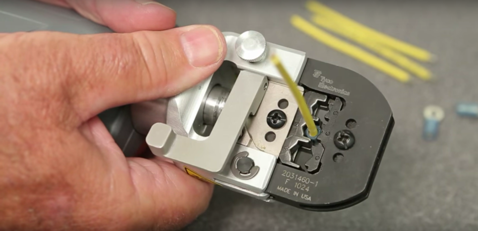
There is something wonderfully primitive about a crimped electrical connection. Take a piece of wire, put it inside a metal terminal, squeeze the terminal with considerable enthusiasm, and somehow you end up with a connection trusted in cars, industrial machinery, aircraft, communications equipment, and even spacecraft.
It sounds almost suspiciously simple. Where is the solder? Where is the flux? Where is the tiny wizard responsible for keeping the electrons inside?
The real explanation is much more interesting. A properly made crimped connection works because carefully controlled mechanical deformation transforms loose strands and a metal barrel into a compact, electrically conductive, mechanically stable joint. Contact pressure, plastic deformation, oxide disruption, friction, strain relief, and material properties all contribute to whether that connection survives ten minutes on a workbench or decades inside a vibrating machine.
Understanding the physics of crimping also explains why professional crimp tools can seem absurdly specific. The terminal, wire gauge, conductor material, die geometry, strip length, and final crimp dimensions are all parts of the same engineered system.
What Actually Happens When You Crimp a Wire?
Before crimping, the situation is unimpressive. A stranded copper conductor sits loosely inside a copper or copper-alloy terminal barrel. Although the wire and terminal appear to touch, microscopic inspection would show that their true metal-to-metal contact area is relatively small.
Metal surfaces are not perfectly smooth. They contain microscopic peaks, valleys, contamination, and oxide films. Electrons therefore do not get the luxurious eight-lane highway suggested by the visible dimensions of the terminal. They must travel through numerous tiny contact points.
Crimping dramatically changes that geometry.
As the dies close, pressure rises until the terminal barrel and conductor strands begin to deform plastically. The strands rearrange, flatten against neighboring strands, and press tightly against the barrel. Voids shrink. Surface films are disturbed. The number and size of intimate contact areas increase enormously.
Instead of several loose copper strands rattling around inside a tube, the result becomes a dense mechanical structure.
Plastic deformation is the secret ingredient
Elastic deformation disappears when the force is removed; plastic deformation remains. A spring is mainly elastic. A crushed soda can has undergone substantial plastic deformation. A crimp relies heavily on the second behavioralthough without turning the terminal into something that looks as though it lost a bar fight.
The crimping force exceeds the yield strength of portions of the conductor and terminal. Their shapes permanently change, creating intimate contact throughout the conductor barrel.
At the same time, elastic stresses remain in parts of the assembly. Those residual forces help maintain contact pressure after the crimping dies reopen.
Why High Contact Pressure Means Low Electrical Resistance
For a bulk conductor, electrical resistance is commonly summarized by:
R = ρL/A
where resistance increases with resistivity and length and decreases as cross-sectional area increases.
A connection adds another problem: contact resistance. Because two touching pieces of metal initially meet only at microscopic high points called asperities, current becomes concentrated through limited areas.
Apply sufficient pressure and many of those asperities deform. The real electrical contact area increases, reducing constriction resistance between conductor and terminal.
This is one reason simply pushing a stripped wire tightly into a terminal is not remotely equivalent to crimping it. Fingers cannot produce the controlled pressures and deformation generated by a properly designed die.
Crimp pressure can also break through or displace portions of surface oxide and contamination, exposing cleaner metal underneath. In well-designed connections, tightly compressed regions may become effectively gas-tight, making it difficult for oxygen and contaminants to migrate into critical contact interfaces.
You will sometimes hear a high-quality crimp described as a form of “cold welding.” That description captures part of what is happening at microscopic contact zones, where intense pressure creates exceptionally intimate metallic contact. However, a crimp should not be imagined as one uniform metallurgical weld across its entire cross-section. Its reliability comes from a network of highly compressed interfaces combined with mechanical interlocking and sustained pressure.
The Crimping Sweet Spot
If pressure is good, surely more pressure is better, right?
Electrical engineering would be dramatically easier if reality behaved that politely.
A crimp must fall inside a carefully defined compression window. Too little deformation produces one collection of problems; too much produces another.
Under-crimping
An under-crimped terminal may leave excessive void space between conductor strands. Contact pressure remains low, allowing higher electrical resistance and potentially greater sensitivity to vibration, oxidation, and thermal cycling.
Mechanically, the wire may simply pull out.
Under-crimping is particularly dangerous because a connection can look reasonably respectable from the outside. Electricity may flow normally during initial testing, yet vibration or heating later causes intermittent faults.
Over-crimping
Over-crimping has its own impressive collection of ways to ruin your afternoon.
Excessive compression may damage or sever conductor strands, thin the terminal barrel, produce cracks, create sharp stress concentrations, or reduce the effective conductor cross-section. A terminal that appears extremely tight can therefore be mechanically weaker than a correctly compressed one.
This explains why qualified crimp specifications frequently define a measurable crimp height. Manufacturers such as TE Connectivity and Molex emphasize crimp height because it provides a repeatable indication of how much the conductor barrel has actually been compressed. Pull-force testing is another widely used quality-control method, and NASA workmanship requirements use process verification and tensile testing for critical harness work.
The Terminal, Wire, and Tool Form a System
A professional crimp should not be treated as three interchangeable objects chosen independently from whatever happens to be nearby.
The wire size determines the amount of conductor material that must fit inside the terminal barrel. The barrel dimensions determine how that conductor can be compressed. The die geometry determines the final deformation.
Change one component and the intended crimp geometry may disappear.
This is why connector manufacturers publish approved tooling for particular terminals and wire gauges. DigiKey’s technical guidance similarly emphasizes matching tooling to the contact series and conductor size, while FAA maintenance material describes calibrated or gauged crimp tools and full-cycle mechanisms for aviation wiring.
A pair of generic hardware-store pliers may technically make something flatter. That does not automatically make it an engineered crimp.
Why ratcheting tools matter
Many professional hand crimpers contain a ratchet that prevents the handles from reopening until the dies have completed their intended stroke.
This helps eliminate the classic human process known as “that feels tight enough.”
Full-cycle tools improve repeatability because each termination reaches a controlled die closure. Production equipment goes further, sometimes measuring the force profile throughout the crimping stroke. Crimp-force monitoring systems can detect anomalies such as missing conductor strands, misplaced terminals, or unexpected material conditions.
Open-Barrel, Closed-Barrel, Hex, and Indent Crimps
Not every crimp looks alike because different applications need different deformation patterns.
Open-barrel crimps
Common in automotive and electronic connectors, open-barrel contacts often have separate wings for the conductor and insulation. During crimping, conductor wings fold inward around the stripped strands, frequently producing the familiar B-shaped cross-section.
The insulation wings provide mechanical support but are not intended to carry the electrical current. Their job is strain relief.
Closed-barrel crimps
Ring terminals, butt splices, and many industrial or aerospace contacts use closed barrels. The stripped conductor slides into a tubular barrel before dies compress it.
Depending on the system, deformation may be oval, hexagonal, indented, or another manufacturer-defined shape.
Indent crimps
Machined circular contacts often use several indenters pressing inward from different directions. Multi-indent geometry distributes deformation around the barrel and can produce highly repeatable connections when used with the specified contact, conductor, and positioner.
The important point is not whether a hex crimp is philosophically superior to a B-crimp. The correct geometry is the one engineered and qualified for that terminal system.
The Insulation Crimp Has a Different Job
Many terminals have two visibly distinct crimp zones: the conductor crimp and the insulation support.
The conductor crimp creates the electrical and primary mechanical connection to the copper strands. The insulation crimp holds the cable jacket or insulation so bending forces are not concentrated where the conductor exits the terminal.
That transition matters because flexible wire meeting rigid metal creates a natural stress concentration.
Without adequate strain relief, vibration repeatedly bends the conductor near the end of the barrel. Copper tolerates plenty of bending in normal flexible cable use, but enough repeated strain concentrated at one location eventually causes fatigue failure.
A proper insulation support spreads those forces over a larger region. Think of it as convincing the wire to bend politely instead of snapping repeatedly at one unfortunate spot.
Why Crimps Often Beat Solder in High-Vibration Applications
Solder is excellent when used correctly, but soldering and crimping solve different mechanical problems.
When stranded wire is soldered, molten solder can wick along the conductor beyond the intended joint. Once cooled, the wicked region becomes relatively stiff. Flexing may then concentrate at the boundary between the stiff soldered region and the flexible unsoldered wire.
A correctly designed crimp can avoid creating the same long rigid solder-wicking zone. That is one reason crimped terminations are so common in automotive and aerospace harnesses where vibration is unavoidable.
Crimping also requires no localized heating, flux, or post-solder cleaning. Once a controlled production process is established, crimps can be manufactured rapidly and consistently.
This does not mean “crimp always good, solder always bad.” It means termination methods should be selected according to the connector design and service environment rather than personal loyalty to whichever tool happens to be closest.
Environmental Enemies: Vibration, Heat, Moisture, and Corrosion
The life of an electrical connector is rarely peaceful.
Vehicles vibrate. Industrial equipment shakes. Aircraft cycle through temperature and pressure changes. Outdoor systems face moisture and contaminants. High-current connections heat up and cool down repeatedly.
A good crimp resists these conditions partly because intense compression creates stable contact interfaces and strong mechanical retention.
Fretting and vibration
Small repeated movements between poorly compressed surfaces can cause fretting wear. This can disturb protective finishes and generate oxide debris, eventually increasing contact resistance.
High mechanical compression helps suppress microscopic movement inside the crimp.
Thermal cycling
Every time current heats a conductor, its dimensions change slightly. Different metals and surrounding materials may expand at different rates. Properly designed crimps maintain sufficient contact pressure despite these cycles.
Corrosion
Terminal manufacturers commonly use copper alloys for conductivity and ductility, with tin or other plating to manage corrosion and surface behavior. Hubbell/Burndy and 3M, for example, specify copper construction and corrosion-resistant plating in many compression terminals.
For harsh environments, the finished termination may also require sealing. UL evaluates various categories of wire connectors, including sealed connector systems, under standards intended for particular electrical applications.
How Professionals Judge Crimp Quality
A nice-looking crimp is encouraging. It is not the entire quality program.
Professional wire-harness production may use several inspection and testing methods.
- Crimp-height measurement: Checks whether conductor compression falls within the specified dimensional window.
- Pull-force testing: Measures mechanical retention between wire and terminal.
- Visual inspection: Looks for damaged strands, incorrect conductor brush, poor bellmouth formation, excessive cutoff tabs, misplaced insulation, and terminal deformation.
- Cross-section analysis: A cut and polished crimp reveals strand compression, voids, barrel geometry, and internal defects.
- Crimp-force monitoring: Production presses can compare the force-versus-position signature of each crimp against acceptable limits.
- Electrical testing: Resistance and continuity measurements help verify electrical integrity at the harness or system level.
IPC/WHMA-A-620 provides widely used workmanship and acceptance criteria for cable and wire-harness assemblies, while NASA maintains additional workmanship standards for critical aerospace applications. The existence of these detailed standards should tell us something important: the phrase “just crimp it” is doing a remarkable amount of unpaid labor.
Common Crimping Mistakes
Several failures appear repeatedly in workshops and field repairs.
Using the wrong wire gauge
A barrel designed for a particular conductor range expects a certain volume of copper. Too little conductor may never develop adequate compression. Too much can lead to severe deformation or strand damage.
Stripping too much insulation
Excessive exposed conductor can leave strands unsupported or positioned incorrectly. Too little strip length may place insulation inside the conductor crimp, preventing proper electrical contact.
Damaging strands during stripping
Nicked or severed strands reduce conductor cross-section and weaken mechanical performance. A beautiful crimp cannot magically restore copper that was chopped off before the terminal reached the tool.
Crimping with ordinary pliers
Pliers provide pressure but usually lack the calibrated geometry, terminal support, stroke control, and repeatability of an application-specific crimp tool.
Adding solder to “improve” a crimp
If the connector manufacturer specifies a crimp termination, adding solder is not automatically an upgrade. Solder can wick into the conductor, change flexibility, alter strain relief, and interfere with the mechanical system the terminal was designed to use.
Practical Experiences: What Working With Crimps Quickly Teaches You
One of the most common workshop experiences with crimped connections begins with skepticism about tooling. A hobbyist or junior technician sees two crimpers on a bench: a basic stamped tool costing little and a ratcheting application tool costing substantially more. Both appear capable of squeezing metal. The expensive one therefore looks suspiciously like an elaborate conspiracy involving tool catalogs.
Then comes the pull test.
A terminal made with the generic tool may survive a casual tug yet slide off when meaningful force is applied. The properly matched ratcheting tool produces a termination that feels completely different. Pull hard enough and the conductor itself may become the limiting element rather than the crimp simply releasing its grip.
That demonstration tends to convert skeptics remarkably quickly.
Another useful bench experience comes from cutting crimps apart. Externally, two terminals may look almost identical. Saw through them, polish the cross-sections, and suddenly the differences become obvious. One contains tightly compacted strands with consistent deformation. Another contains large voids, oddly displaced conductors, or a barrel that has barely compressed the wire.
It is a good reminder that electrical reliability frequently hides beneath surfaces nobody sees after assembly.
Automotive troubleshooting provides another lesson. An intermittent electrical fault is often blamed first on software, sensors, modules, or whichever expensive component can generate the most dramatic invoice. Yet vibration-sensitive problems may eventually lead technicians back to a wire termination. Moving the harness changes the symptom. Measuring voltage drop under load reveals unexpected resistance. Opening the connector finally exposes a loose or damaged crimp.
The connection may have passed continuity testing because an unloaded multimeter requires almost no current. Under real load, however, even modest added resistance creates voltage drop and heating. The difference between “continuity exists” and “this connection can reliably carry current” is an important practical lesson.
Production environments add another experience: consistency matters more than heroics. A highly skilled operator might make an excellent terminal using a manual tool once. Manufacturing needs thousands of excellent terminals repeatedly. That is why factories care about calibrated tooling, crimp-height measurements, applicator maintenance, pull-force sampling, force monitoring, and statistical process control.
Finally, crimping teaches healthy respect for instructions that initially seem overly specific. Strip the wire this far. Use this contact with this gauge. Position it here. Use this die. Measure this dimension.
It can feel fussy until you remember what the terminal may eventually be doing: carrying power beside a hot engine, operating inside vibrating industrial machinery, supporting critical avionics, or remaining untouched inside equipment for twenty years.
At that point, a few thousandths of an inch of controlled deformation suddenly stop looking fussy.
They look like engineering.
Conclusion: A Small Joint With Serious Physics
The physics of crimped connections demonstrates how much engineering can hide inside a deceptively simple mechanical operation. Reliable crimping depends on plastic deformation, sustained contact pressure, increased real metal-to-metal contact area, mechanical retention, strain relief, corrosion control, and carefully matched materials and tooling.
The best crimp is neither the loosest nor the most brutally crushed. It sits inside an engineered compression window where electrical resistance remains low while mechanical strength remains high.
That is why professional crimping specifications care about details such as crimp height, pull force, wire preparation, die geometry, insulation position, and tooling calibration. In applications where vibration, temperature changes, moisture, or long service life matter, those details are what transform a squeezed piece of metal into an exceptionally dependable electrical connection.
So yes, crimped connections are literally good in a pinch. But the pinch is considerably more sophisticated than it looks.
Note: Crimp dimensions, approved wire ranges, tooling, pull-force requirements, and inspection criteria vary by connector system. For safety-critical or high-current work, always follow the terminal manufacturer’s specified application tooling and relevant wiring standards.