Modern screens can display millions of colors, play video, recognize touch, and probably judge your choice of wallpaper. Yet a tiny red display technology from the 1970s continues to fascinate electronics enthusiasts. Classic LED bubble displays are glowing again, this time connected to Arduino boards, FPGAs, custom PCBs, and other hardware their original designers could scarcely have imagined.
The Return of a Tiny Red Electronics Icon
LED bubble displays belong to an era when digital electronics looked unmistakably electronic. Their miniature red characters sat beneath clear molded lenses that enlarged the light-emitting segments. The result was bright, crisp, slightly futuristic, and wonderfully different from the flat screens surrounding us today.
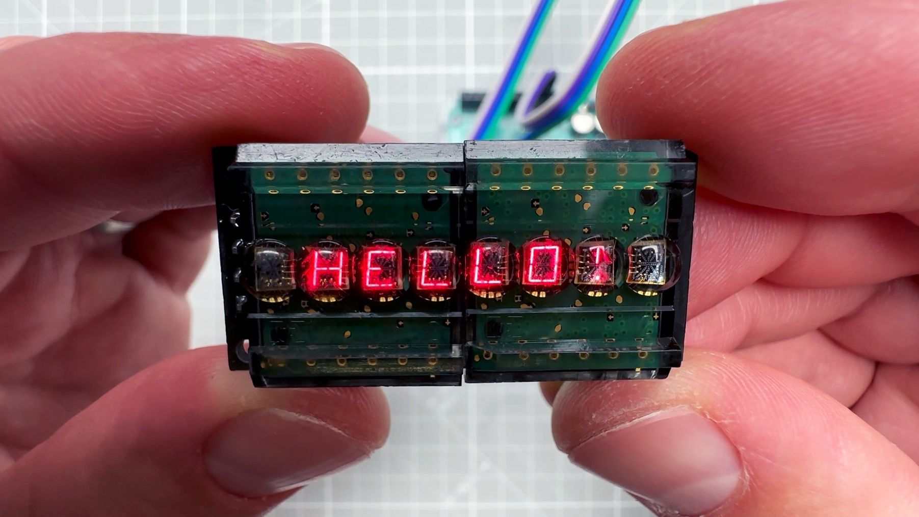
A recent revival centered on the HPDL-1414, an alphanumeric Hewlett-Packard display containing four characters beneath individual magnifying lenses. A maker known as Upir obtained a module carrying two of these displays, connected it to an Arduino Uno, deciphered the module’s interface, and brought all eight characters back to life. The project demonstrated letters, numbers, punctuation, and simple animated sequences while preserving the unmistakable visual personality of the original hardware.
The module is especially interesting because it combines old and new technology. The HPDL-1414 devices themselves are vintage parallel-input alphanumeric displays, but the carrier board adds an interface that can be controlled from a modern microcontroller. It is essentially a technological time machine with header pins.
What Is an LED Bubble Display?
Small LEDs Viewed Through Magnifying Lenses
A bubble display places tiny LED segments or dots beneath a transparent package molded with curved lenses. Each lens magnifies one character, making a very small emitting area easier to read. The “bubble” is therefore not decorative plastic added for retro charm. It performs a real optical job.
Many early versions were seven-segment numeric displays. Seven bars form numerals from zero through nine, while an additional LED may provide a decimal point. Other models used more segments or dot matrices to display letters and symbols. The HPDL-1414, for example, is an alphanumeric device rather than the simpler calculator-style numeric stick commonly associated with bubble displays.
Several Families, Not One Universal Part
The term bubble display describes a visual construction style, not one standardized electrical design. Hewlett-Packard’s 5082-7300 family included individual numeric and hexadecimal indicators with built-in decoding, driving, and memory. The 5082-7400 family included multiplexed multidigit modules. Devices such as the QDSP-6061 and QDSP-6064 grouped several common-cathode seven-segment digits in compact packages. The HPDL-1414 offered four alphanumeric characters with internal character-decoding circuitry.
That distinction matters. A driver circuit designed for one part may be completely unsuitable for another, even when both parts have charming little lenses and the same deep-red glow. Before applying power, builders should identify the exact model, locate its datasheet, and confirm its pinout. Vintage components are difficult enough to replace without turning one into an eight-legged smoke machine.
Why Bubble Displays Became Famous
The Pocket Calculator Revolution
Early handheld calculators gave bubble LED displays their most memorable stage. Hewlett-Packard introduced the HP-35 in 1972 as the first handheld scientific calculator, offering logarithmic, trigonometric, and exponential functions in a device small enough to carry. Its red LED display helped create the visual language of advanced pocket electronics. The calculator quickly challenged the slide rule as an everyday engineering tool.
Other manufacturers adopted similar red LED displays for calculators, watches, test instruments, terminals, and laboratory equipment. The glowing digits looked precise and modern, particularly against dark filters that improved contrast. To a 1970s buyer, a pocket device performing scientific calculations in red light was not merely useful. It was a small slab of the future.
A Compact Demonstration of Early Integration
Some Hewlett-Packard indicators were more sophisticated than a bare array of LEDs. Documentation for the 5082-7300 series describes a 7.4-millimeter numeric or hexadecimal character, TTL-compatible inputs, an internal decoder and driver, and latch memory. A four-bit input could therefore select a digit without requiring the host circuit to control every dot separately. The recommended supply was a nominal five volts, while the emitted red light had a peak wavelength listed around 655 nanometers.
Those features reduced the component count in instruments and terminals. They also make certain vintage displays surprisingly approachable today. A microcontroller can present the required data and control signals while the original device handles the character pattern.
Why the Original Displays Disappeared
LED displays offered excellent visibility, but continuous illumination required meaningful power. That was an inconvenient personality trait for equipment expected to run on small batteries. Liquid-crystal displays eventually became the practical choice for calculators and watches because they could present information using far less energy.
Manufacturing priorities also changed. Larger, cheaper seven-segment modules became common, while character LCDs and later OLED panels provided more information with easier interfaces. Specialized bubble packages turned into obsolete inventory rather than mainstream components. Many surviving examples now come from surplus stock, dismantled equipment, old university laboratories, or the mysterious drawer every electronics hobbyist owns but refuses to organize.
Obsolescence, however, created scarcity, and scarcity created affection. Bubble displays are now collected because they are attractive artifacts as well as functional components. Their limitations are part of the appeal. A display that can show only a few glowing characters forces a project to have focus.
How Modern Makers Bring Bubble Displays Back
Start With the Datasheet
The first step is identifying supply voltage, segment current, logic thresholds, common-anode or common-cathode construction, and control timing. Some displays accept encoded character data. Others require direct segment driving and rapid multiplexing. Vintage documentation may be scanned, faint, or marked with several closely related part numbers, so careful reading is not optional.
The Upir project illustrates another common challenge: the display may be mounted on an undocumented third-party board. The bare HPDL-1414 has its own parallel interface, while the assembled module introduces additional control electronics. Reverse engineering may involve tracing PCB connections, translating labels, observing serial data, and testing character codes cautiously.
Use Current-Limiting Resistors and Proper Drivers
LED segments require controlled current. A microcontroller pin should not be connected blindly to an unknown vintage display. Depending on the part, a project may need resistors, bipolar transistors, MOSFETs, shift registers, or a dedicated LED driver.
A modern driver PCB for HP 5082-7400-series displays uses two 74HC595 shift registers. One selects the active digit cathode, while the other controls segment anodes through resistors. This approach reduces the number of microcontroller connections and makes multiple modules easier to stack.
Multiplex Faster Than the Eye Can Follow
In a multiplexed display, digits are not necessarily illuminated at the same instant. The controller activates one digit, sends its segment pattern, switches it off, and moves to the next. Repeating this process quickly produces the appearance of a steady display.
The refresh rate must be high enough to avoid visible flicker but not so aggressive that switching artifacts, ghost segments, or excessive current appear. Firmware should usually blank the display briefly while changing digit and segment signals. Without that step, a clock may show the correct time plus several paranormal fragments from the previous digit.
Microcontrollers and FPGAs Both Work
Arduino-class boards make bubble display projects accessible because they provide simple digital I/O, timing functions, and large community libraries. One Arduino Project Hub build connected a six-digit NSA1166 display to an Arduino MKR WiFi 1010, while another retro calculator combined an MSP430 microcontroller, an ICM7228 driver, a matrix keypad, and a custom circuit board.
FPGAs offer extremely precise control over multiplexing and parallel signals. A QDSP-6061 project used an Arty Z7 board, external transistors, and segment resistors to operate a five-digit common-cathode display. The designer first determined the undocumented pinout and then created the required control logic in programmable hardware.
Why the HPDL-1414 Revival Is Special
Most familiar bubble displays are numeric, but the HPDL-1414 can form letters and symbols using a segmented alphanumeric structure. Four characters fit into one compact dual-inline package, and each character sits under its own lens. Put two packages together and the result is an eight-character message display that resembles a miniature terminal from a science-fiction control room.
The display’s internal character generator accepts supported character codes and converts them into segment patterns. That reduces the work required from the host processor, although the available character set is fixed by the original hardware. Lowercase text and modern symbols may therefore require substitutions. The limitation becomes a design feature: messages look best when they are short, bold, and slightly robotic.
The recently demonstrated module adds a serial control layer around the vintage displays. Once the communication format and character mapping were understood, an Arduino could send text and animations without directly managing every segment. The finished result demonstrates an important principle of hardware preservation: old components do not always need to remain inside museums or sealed bags. With sensible electrical protection, they can perform again.
Great Projects for Vintage Bubble LED Displays
Retro Desk Clock
A clock is the natural home for a multidigit bubble display. A real-time clock module can maintain accurate time, while a microcontroller handles multiplexing, brightness, and button input. Builders have created numerous clocks from 1970s display modules, often pairing the red digits with brushed aluminum, dark acrylic, or walnut enclosures.
Compact Calculator
A custom calculator lets the display return to its ancestral habitat. Modern processors make the arithmetic easy; the real design challenge is presenting signed values, decimal points, overflow, and error messages within a limited number of characters. That constraint encourages thoughtful interaction design rather than another touchscreen covered with tiny buttons.
System Monitor
An alphanumeric bubble display can show CPU temperature, network status, voltage, radio frequency, or short alert messages. It will not compete with a dashboard monitor for information density, but it will make “TEMP 42C” look like a warning from a moon base.
Retrocomputer Front Panel
Bubble displays are ideal for home-built eight-bit computers, hexadecimal trainers, memory viewers, and bus monitors. Numeric or hexadecimal indicators can present addresses and data values, while alphanumeric modules can display operating states and commands. The RC2014 community even developed a module capable of driving selected Hewlett-Packard bubble displays from a modern retrocomputer bus.
Conversation-Piece Name Badge
An eight-character alphanumeric module can become a desktop nameplate or wearable badge, provided the power source and enclosure are practical. Scrolling a name, job title, or deliberately unhelpful message such as “ASK L8R” gives obsolete hardware a social life.
Practical Challenges Before Starting
Vintage Parts Can Be Expensive
These displays are no longer ordinary catalog items. Prices vary widely, and sellers may not know whether a component has been tested. Purchasing several matching units can be difficult, particularly when brightness categories, package revisions, or date codes differ.
Cosmetic Condition Matters
Scratched lenses, bent leads, faded filters, internal corrosion, and uneven brightness are common. The clear package should be cleaned conservatively because strong solvents may damage or craze older plastics. A soft cloth and material-compatible cleaner are safer than attacking forty-year-old acrylic with whatever bottle happens to be nearest the soldering iron.
Logic Levels May Not Match
Many vintage displays were designed around five-volt TTL systems. A contemporary microcontroller may use 3.3-volt logic and may not tolerate five volts on its inputs. Level shifting, transistor stages, or compatible buffer chips may be necessary. The fact that two pins physically touch does not mean they have entered into a healthy electrical relationship.
Documentation Can Be Incomplete
Exact datasheets are invaluable, but hobbyists sometimes encounter unlabeled modules or carrier boards with unknown controllers. Continuity testing, current-limited bench supplies, oscilloscopes, and logic analyzers can help. Begin with conservative current limits and document every confirmed connection before moving to the next.
Experiencing a Bubble Display Revival on the Workbench
Working with a classic LED bubble display feels different from assembling a project around a modern plug-and-play screen. A new OLED module often arrives with a clearly labeled connector, an active software library, and enough online examples to get it displaying text before lunch. A vintage bubble module may arrive in an anti-static bag carrying a faded handwritten part number and the quiet implication that mistakes will be expensive.
The experience typically begins with inspection rather than soldering. The builder checks the package for cracks, straightens bent pins carefully, and searches for a recognizable manufacturer code. Finding a matching datasheet feels like discovering a treasure map, except the treasure is a pin labeled “latch enable.” Related part numbers must be compared because one model may place the decimal point on the opposite side, add blanking control, or use an entirely different internal structure.
First power-up should be deliberately boring. A current-limited bench supply is set to the specified voltage, logic inputs are placed in known states, and the current limit remains conservative. Then one digit or character appears. It may be dim under room lighting, but viewed through its tiny lens it has a sharpness that photographs rarely capture. The glow seems to sit below the package surface, like a miniature instrument panel seen through glass.
The next stage is usually less poetic. A segment refuses to light. Two digits appear simultaneously. The display shows an “8” when the software requested a “3.” The builder checks the wiring, discovers that two address lines were reversed, and learns once again that breadboard jumper colors are not a substitute for documentation.
Once basic control works, brightness becomes the obsession. Multiplex too slowly and the display flickers. Increase the refresh rate without correct blanking and ghost segments appear. Raise current carelessly and the characters become brighter, but the irreplaceable component also becomes warmer. The best result usually comes from balanced timing, suitable resistors, and a dark contrast filter rather than brute-force current.
Mechanical design is another part of the experience. The display may look awkward on a large breadboard but spectacular behind a smoked acrylic window. A compact PCB transforms a nest of wires into something resembling a finished instrument. Period-inspired controlsmetal buttons, rotary switches, textured plastic, and engraved labelscan complement the display without turning the project into a costume.
Finally, the builder writes a demonstration routine. Digits count upward. Letters march across the lenses. A clock colon blinks. A short message scrolls past, constrained by the character set and the tiny number of positions. That limitation encourages experimentation: abbreviations, simple animations, hexadecimal patterns, and transitions that exploit the segmented construction.
The lasting impression is not that bubble displays outperform modern screens. They plainly do not. The pleasure comes from understanding every visible action. Each character represents voltage levels, latches, segment patterns, multiplex timing, and optical magnification working together. The display does one modest job, but it performs that job with enough personality to make an entire project memorable.
That is why classic LED bubble displays ride again. They connect electronics history with modern maker culture, reward careful engineering, and turn a few red characters into a genuine event. In a world of disposable displays, bringing a component from the 1970s back to life feels less like installing a screen and more like waking up a very small robot.
Conclusion: Old Displays, New Possibilities
The revival of the HPDL-1414 and related bubble LED displays proves that obsolete technology does not have to become useless technology. These components remain valuable teaching tools for digital logic, LED driving, multiplexing, reverse engineering, PCB design, and embedded programming.
They also remind us that visual character matters. A modern display may offer vastly better resolution and efficiency, but a row of magnified red segments has an identity that cannot be reproduced perfectly by drawing a retro font on an LCD. The light is physical, the limitations are real, and the result is unmistakably alive.
For makers willing to study a datasheet, protect old hardware, and tolerate a little jumper-wire archaeology, classic LED bubble displays offer one of the most satisfying bridges between computing history and contemporary electronics.