At first glance, “audio out over a UART” sounds like a prank a bored engineer would write on a whiteboard five minutes before lunch. UART is supposed to move serial data. Audio is supposed to come from a DAC, sound card, codec, amplifier, or at least something that looks like it belongs near a speaker. Yet with an FTDI USB-to-TRS cable, a little signal math, and the courage to plug a serial cable into an audio input, you can make recognizable sound come out of a device that was never marketed as a sound interface.
This project is a beautiful reminder that electronics often cares less about labels and more about voltage over time. A UART transmit pin does not know whether it is “debugging firmware” or “trying to sing.” It only toggles between logic levels at a controlled rate. If those toggles are shaped into a dense one-bit stream, and an audio input filters them into an analog waveform, the result can be surprisingly listenable. Not studio-grade, not “mastered at Abbey Road,” but absolutely real audio.
What Is an FTDI USB-To-TRS Cable?
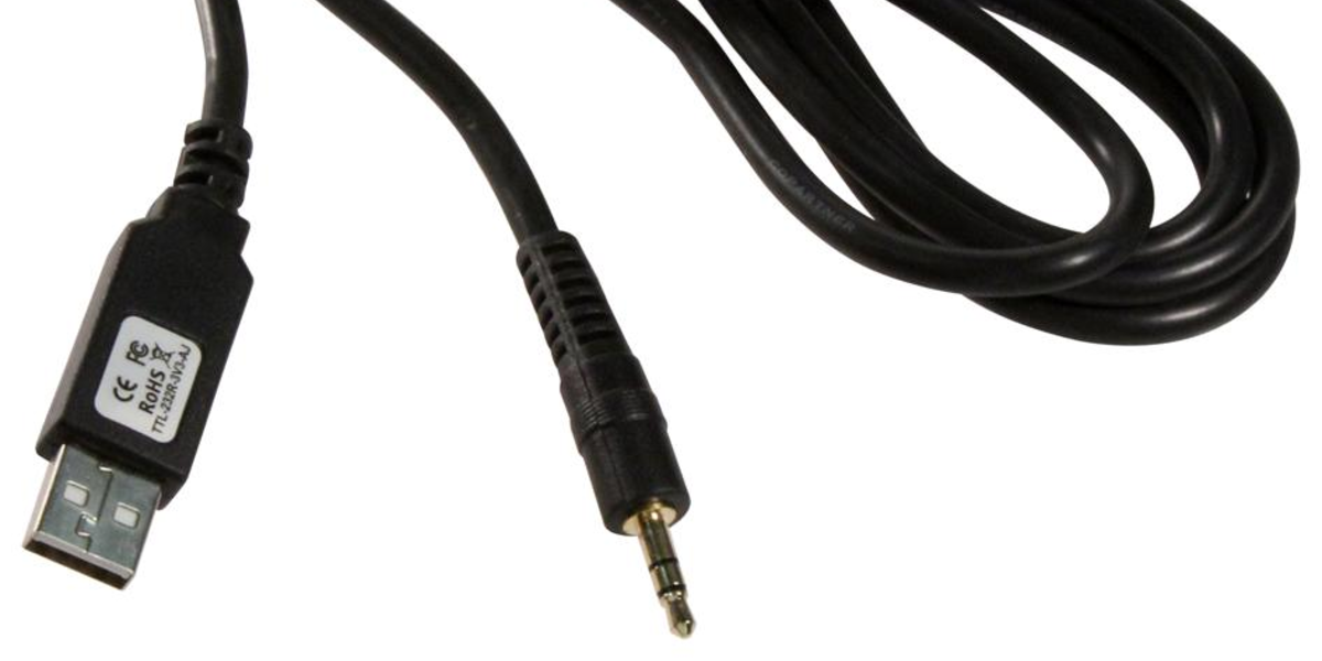
The cable commonly used for this trick is the FTDI TTL-232R-3V3-AJ, a USB-to-UART adapter with a USB Type-A connector on one end and a 3.5 mm audio-style plug on the other. The “AJ” in the part name points to the audio-jack form factor, but that is where many beginners get ambushed by assumptions. This is not a USB sound card. It does not output left and right analog audio like your laptop headphone jack. It is a TTL serial cable that happens to use a TRS plug as a convenient connector.
The cable supports 3.3V UART signaling, uses an FT232R USB-to-serial chip internally, and can run up to 3 Mbaud on the UART side. The USB side runs at full-speed USB. In normal life, this cable connects a computer to embedded hardware, routers, development boards, test fixtures, or any gadget with RX, TX, and ground available through a jack. In this odd little audio experiment, the TX line becomes the “audio” source.
Why a TRS Plug Makes the Hack Possible
A standard 3.5 mm TRS audio plug has three conductors: tip, ring, and sleeve. In normal stereo audio, the tip usually carries the left channel, the ring carries the right channel, and the sleeve is ground. In the FTDI cable, those same metal sections are repurposed for UART signals. The important overlap is ground. If the cable’s ground aligns with the audio device’s ground, and the UART TX line lands where an audio channel expects a signal, the audio input will see a fast-changing voltage.
That does not mean every 3.5 mm jack is fair game. Some devices use TRRS headset wiring. Some microphone inputs provide bias voltage. Some portable devices expect tiny microphone-level signals rather than line-level input. Some amplifiers are more forgiving than others, while some are expensive enough to make experimentation feel like defusing a tiny financial bomb. The safest target is a line-level input on inexpensive gear, ideally with a series resistor and a conservative volume setting.
How UART Can Pretend to Be Audio
UART stands for Universal Asynchronous Receiver-Transmitter. In ordinary use, it sends bytes one at a time using a start bit, a configurable number of data bits, optional parity, and one or more stop bits. A common format is 8N1: one start bit, eight data bits, no parity, and one stop bit. The TX line idles high, dips low for the start bit, sends the data bits, and returns high for the stop bit.
For data communication, those timing details help a receiver reconstruct bytes. For audio hacking, those same timing details become a stream of pulses. If you simply dumped random bytes over the serial port, the output would mostly sound like digital confetti. The clever part is converting audio samples into a pattern of ones and zeros whose density represents the intended waveform.
PCM, PDM, and the Magic of Pulse Density
Most WAV files store audio as PCM, or pulse-code modulation. PCM represents the amplitude of the waveform at each sample point. For example, a 16-bit mono WAV file at 44.1 kHz stores 44,100 amplitude values per second. That is wonderfully straightforward for software and audio hardware, but a UART TX pin cannot output an arbitrary analog voltage. It can only switch between low and high.
Pulse-density modulation, or PDM, solves the problem in a wonderfully sneaky way. Instead of saying “the voltage should be exactly this value,” PDM says “use more high pulses for a higher signal and fewer high pulses for a lower signal.” Over a short window of time, the average density of pulses approximates the desired analog level. A low-pass filter then smooths the rapid switching and leaves behind the slower audio waveform.
Many audio inputs already include filtering, bandwidth limits, coupling capacitors, and amplifier stages that naturally reject very high-frequency switching. That is why a PDM-like stream sent through a UART can become audible when plugged into a line input. The receiver is not decoding UART. It is simply being fed a fast pulse train and doing what analog audio circuits often do best: ignoring the nonsense above the audio band.
Why the Baud Rate Matters
Baud rate is the heartbeat of the entire trick. At 3 Mbaud, each serial bit lasts roughly one-third of a microsecond. With 8N1 framing, every byte consumes ten bit times, so the line can carry about 300,000 framed bytes per second under ideal conditions. The audio encoder must respect this timing because the output pulse stream depends on the UART bit rate.
If the PCM input file has the wrong sample rate, the conversion may play too fast, too slow, or with unpleasant artifacts. A practical workflow usually begins by converting a WAV file to the required mono sample rate and bit depth, then running an encoder that maps the PCM waveform into serial-friendly PDM data. Once the output file is generated, software can write it directly to the FTDI virtual serial port.
A Practical Example Workflow
Imagine you have a short mono WAV file and want to play it through the FTDI USB-to-TRS cable. First, you convert the audio to the sample rate expected by your encoder. You keep the file short, because nobody needs to debug a ten-minute guitar solo on the first attempt. Next, the encoder reads the PCM samples and produces a raw byte stream designed for the UART framing pattern.
Then you open the FTDI serial port at the required baud rate using a tool such as a small C program, Python with pySerial, or a command-line utility that can write binary data without adding line endings. The cable’s TRS plug goes into a line input, not a headphone output, not a speaker output, and definitely not a random mystery jack labeled with an icon that looks like a shrimp. Start with the amplifier volume low, begin playback, and gradually raise the level.
What It Sounds Like
The result can be shockingly good for something that looks electrically mischievous. Speech is often easier to recognize than music because the human ear is forgiving with voices. Simple melodies, chiptune-style audio, and test tones can come through clearly. Dense music may reveal noise, aliasing, hiss, and high-frequency grit, especially if the receiving audio device does not filter the pulse stream gracefully.
This is not a replacement for a DAC. A real DAC provides proper analog output, predictable impedance, stereo capability, better dynamic range, lower noise, and far fewer reasons for your amplifier to question your life choices. But as a hardware hack, UART audio is fantastic. It turns a serial adapter into a one-bit audio source and teaches more about digital audio than a dozen tidy block diagrams.
Safety Considerations Before You Plug Anything In
The most important rule is simple: do not connect the cable to anything valuable until you understand the wiring and levels. The 3.3V adapter version is far more reasonable than a 5V serial output for this experiment, but 3.3V logic is still hotter than typical consumer line-level audio. Consumer line level is commonly around -10 dBV, while professional line level is commonly +4 dBu. A raw logic signal can be far larger than either, even if filtering and input impedance reduce the drama.
A series resistor is a smart precaution because it limits current and reduces the chance of abusing the input stage. A coupling capacitor can help block DC, especially because UART idle state is high and therefore carries a DC component before filtering. A simple low-pass RC filter can also improve sound quality and reduce ultrasonic energy. If you want the experiment to be tidy instead of feral, build a small adapter box with attenuation, filtering, and clearly labeled connectors.
Common Mistakes
Assuming the cable is an audio adapter
The 3.5 mm plug is only a connector shape. The cable is still a USB-to-UART interface. Treating it like a headphone output is the fastest way to become confused.
Using the wrong input
A line input is the right target. A microphone input may overload easily, and a headphone output is not an input at all. Plugging output into output is not “full duplex”; it is electronic awkwardness.
Ignoring baud rate and sample rate
The encoded stream depends on timing. Change the baud rate without changing the encoding and the pitch or speed may shift. Change the input sample rate without resampling and the output may become a tiny robot trapped in a blender.
Expecting stereo sound
Most versions of this trick use the UART TX line as a single signal path. The right audio channel is typically unused unless you build a more complex arrangement with additional output pins and carefully synchronized streams.
Why This Hack Matters
The real value of audio out over UART is not that it produces the world’s most luxurious sound. The value is educational. It connects serial communication, digital modulation, audio filtering, signal levels, connector wiring, and driver behavior in one unforgettable experiment. Once you hear music coming out of a UART pin, the line between “digital” and “analog” stops feeling like a brick wall and starts looking more like a translation problem.
It also demonstrates a practical engineering mindset: use what is available, understand the constraints, and let physics do part of the work. A UART is not designed as a DAC, but it is a timed one-bit output. A line input is not designed as a PDM decoder, but it filters and amplifies changing voltage. Put those two facts together, and suddenly a debug cable can perform a party trick worthy of a soldering bench standing ovation.
Hands-On Experience Notes: What It Feels Like to Build and Test
The first experience most people have with this project is suspicion. You hold the FTDI USB-to-TRS cable in one hand and an audio input in the other, and your brain politely asks whether this is engineering or cable-based nonsense. That hesitation is healthy. The trick works best when approached like a lab experiment: verify the cable pinout, confirm the serial port name, set the baud rate intentionally, and test with cheap speakers before involving anything with a brushed aluminum faceplate and emotional value.
A good first test file is not your favorite song. Use a short sine wave, a spoken phrase, or a simple melody. Short files make troubleshooting easier because you can quickly tell whether the stream is playing at the wrong speed, clipping, or producing only silence. If the sound is too harsh, reduce input gain, add attenuation, or try a small RC filter. If the playback is too fast or slow, revisit the relationship between the WAV sample rate and the UART baud rate. Most “broken” tests are not truly broken; they are timing mismatches wearing a fake mustache.
One practical lesson appears quickly: binary output must remain binary. Some terminal tools are designed for text and may insert carriage returns, line feeds, buffering behavior, or character translation. That is charming for humans and terrible for raw audio streams. Use software that writes bytes exactly as generated. In Python, open the serial port with the correct baud rate and write the encoded data as bytes, not as strings. In C, avoid functions that treat zero bytes as the end of text. Audio data does not appreciate being handled like a polite email.
Another lesson is that the receiving amplifier matters. One speaker may smooth the stream nicely and sound surprisingly clean, while another may reveal more switching noise. A laptop line input, a powered desktop speaker, and a small practice amp can all behave differently because their input circuits are different. That variability is not failure; it is the analog half of the project making a cameo appearance.
The most satisfying moment is hearing a recognizable voice or melody from a cable that was supposed to be used for firmware logs. It feels like finding a secret passage in a familiar building. The project is not merely a stunt; it teaches timing, modulation, filtering, and respect for voltage levels. It also gives you a story that begins, “I played audio through a UART,” which is an excellent way to either impress engineers or make normal people back slowly out of the room.
Conclusion
Audio out over a UART with an FTDI USB-to-TRS cable is a clever, slightly rebellious hardware hack that turns a serial TX pin into a one-bit audio source. By converting PCM audio into a PDM-like stream and sending it at a carefully chosen baud rate, the cable can feed a line-level audio input with pulses that become audible sound after filtering. It is not hi-fi, and it should be tested carefully, but it is a brilliant example of how digital timing and analog behavior can meet in the middle.
For makers, embedded developers, audio experimenters, and anyone who enjoys making hardware do jobs it was not hired for, this project is worth studying. It explains UART framing, PDM encoding, line-level audio, connector pinouts, and practical signal safety in one compact adventure. The FTDI cable may not be a sound card, but with the right data and a little caution, it can still sing.