A current probe is one of those tools that looks suspiciously simple until you use one correctly and suddenly feel like you have unlocked a secret room in electronics troubleshooting. Instead of cutting a wire, inserting a shunt resistor, praying your ground clip does not become a fireworks sponsor, and then doing math while squinting at your oscilloscope, a current probe lets you clamp around a conductor and watch current as a waveform. That is the dream. The “budget” version of that dream, however, usually arrives with a few charming personality traits: offset drift, limited bandwidth, mysterious noise, calibration quirks, and a manual that appears to have been translated through four languages and a toaster.
Still, budget current probes are not useless. Far from it. For electronics hobbyists, repair technicians, students, and engineers who do not want to spend the price of a used motorcycle on a premium oscilloscope current probe, a lower-cost probe can be an excellent diagnostic tool. The trick is knowing what is inside, what it can measure well, what it cannot measure honestly, and when its waveform is telling you the truth versus performing experimental jazz.
This deep dive explains what is inside a budget current probe, how it works, why AC and DC current measurement require different sensing methods, what specifications actually matter, and how to use one without being fooled by the little gremlins hiding in the jaws.
What Is a Current Probe?
A current probe is a measuring accessory that converts electrical current into a voltage signal your oscilloscope, multimeter, or data acquisition device can understand. Instead of measuring voltage across a component, it senses the magnetic field produced by current flowing through a conductor. That magnetic field becomes a signal, and the probe outputs something like 10 mV per amp, 100 mV per amp, or another scale factor depending on the model.
The biggest advantage is convenience. You do not need to break the circuit. You do not need to insert a resistor. You do not need to redesign a board just to find out whether a motor driver is sipping current politely or gulping it like a teenager at a soda fountain. Clamp the probe around one conductor, zero it, set the scale, and view the waveform.
Current probes are especially useful for power electronics, motor control, battery-powered devices, switching regulators, LED drivers, automotive troubleshooting, robotics, audio amplifiers, and anything with pulsed or changing current. They help answer practical questions: Is the inrush current too high? Is the buck converter saturating its inductor? Is a motor stalling? Is a device waking from sleep too often? Is a MOSFET switching cleanly? A current probe turns these invisible behaviors into a visible shape.
What Makes a Probe “Budget”?
The word “budget” does not automatically mean bad. It means compromises. A premium current probe from a major test-equipment company may offer high bandwidth, low noise, precise calibration, excellent shielding, fast overload recovery, strong mechanical alignment, and direct communication with compatible oscilloscopes. A budget current probe usually skips some of that polish to hit a much lower price.
Common budget-probe compromises include lower bandwidth, more noise at small current levels, weaker jaw alignment, more temperature drift, less accurate zeroing, limited documentation, and less predictable phase response. Some probes may be perfectly useful at 50 Hz, 60 Hz, or low-kilohertz switching work, but become questionable when asked to capture sharp switching edges from modern power electronics.
In simple terms, a budget current probe often tells you the general story very well: current goes up here, drops there, spikes at startup, oscillates under load, or changes when the firmware wakes a circuit. But it may struggle with the fine print: exact peak current, nanosecond-level timing, tiny standby current, or clean high-frequency detail.
Inside the Probe: The Magnetic Core
Open a typical clamp-style current probe and the most important mechanical feature is the magnetic core. The jaws are not just plastic pinchers; they contain shaped magnetic material, often ferrite or laminated magnetic alloy, designed to guide magnetic flux around the conductor being measured. When current flows through the wire, it creates a magnetic field. The core concentrates that field so a sensing element can detect it.
This is why jaw alignment matters. The two halves of the core must close cleanly. If dirt, oxidation, wear, or poor molding leaves an air gap, the magnetic path becomes less efficient. Measurement accuracy drops, especially at low current. That is also why current probe manuals often tell you to keep the jaw faces clean. It sounds like boring advice, but it matters. A crumb of debris on the magnetic contact surface can be the difference between a believable waveform and a tiny electrical ghost story.
The conductor under test acts like a one-turn primary winding. The probe core and internal winding or sensor form the secondary measurement system. If you pass the same wire through the jaws multiple times, the measured signal multiplies. Two turns through the jaw doubles the effective current reading; five turns makes a 200 mA signal look like 1 A. This trick is useful when measuring small currents, but only if you remember to divide the displayed value by the number of turns. Forget that step and your circuit will appear dramatically more powerful than it is, which is excellent for ego and terrible for engineering.
AC Current Measurement: The Transformer Side
For AC current, many current probes use transformer action. A changing current creates a changing magnetic field, which induces a voltage or current in a secondary winding. This method is elegant, passive in principle, and can work well over a wide frequency range.
The catch is that transformers do not measure DC. A steady current produces a steady magnetic field, and a transformer needs change to induce a signal. That means a current transformer can show alternating current, pulses, ripple, switching behavior, and other changing current patterns, but it cannot report a pure DC level by itself.
Budget AC-only current probes and current clamps often rely heavily on this transformer principle. They can be very useful for mains-frequency current, audio-frequency current, and some switching measurements. However, their low-frequency response may be limited. If the current changes very slowly, the transformer output droops. On an oscilloscope, a long pulse may start strong and then sag, not because the current is actually fading, but because the probe’s transformer cannot hold the low-frequency content indefinitely.
DC Current Measurement: The Hall Effect Side
To measure DC current without breaking the circuit, a probe needs a different method. This is where the Hall effect enters the room wearing a lab coat. A Hall sensor produces a small voltage when exposed to a magnetic field. Since DC current creates a steady magnetic field, a Hall-effect sensor can detect it.
AC/DC current probes typically combine Hall-effect sensing for DC and low-frequency current with transformer-style sensing for higher-frequency current. The electronics blend these signals so the output represents current from DC through some upper bandwidth limit. In better probes, this transition is carefully engineered. In budget probes, it can be good enough for practical work but may show more offset, drift, and noise.
Hall sensors are sensitive, but they are not magic. They can drift with temperature. They can be affected by residual magnetism in the core. They can respond to nearby magnetic fields. They may need a zero adjustment before each measurement. Many budget probes have a “zero” button or knob because the output can wander even when no conductor is inside the jaws. That is normal. Annoying, yes. But normal.
The Amplifier and Signal Conditioning Circuit
The sensor signal inside a current probe is usually tiny, so it needs amplification and conditioning. A budget current probe may contain a Hall sensor, small amplifier stages, compensation networks, range switching, offset adjustment, and output scaling. Some probes provide a BNC output for oscilloscopes. Others connect to a multimeter or have a built-in display.
Range switching is important. A probe may offer a high-sensitivity range for smaller currents and a lower-sensitivity range for larger currents. For example, one range might output 100 mV per amp, while another outputs 10 mV per amp. The higher-sensitivity range gives better visibility for low current but clips or saturates sooner. The lower-sensitivity range handles larger current but makes small signals harder to see.
Good signal conditioning also controls noise and bandwidth. If the probe is too wide open, it may show noise that makes the waveform look hairy. If it is filtered too aggressively, it may hide real fast events. Budget probes often choose a middle path: useful enough for everyday troubleshooting, not precise enough to replace laboratory-grade equipment.
Bandwidth: The Specification Everyone Misunderstands
Bandwidth tells you how fast a signal the probe can accurately follow. A current probe advertised with a 20 MHz bandwidth should, in theory, measure current waveforms up to that region with a specified amplitude response. But bandwidth does not mean every waveform below that frequency will look perfect. Fast edges contain harmonics far above the basic switching frequency.
For example, a switching regulator running at 500 kHz may produce sharp current transitions. Even though 500 kHz sounds far below 20 MHz, the edge details may require much more bandwidth to reproduce accurately. A budget probe may still show the current ramp and switching pattern, but the peaks may look rounded, delayed, or lower than reality.
This matters when diagnosing power electronics. If you are checking whether an inductor current is triangular, whether a MOSFET has a severe current spike, or whether a motor phase current is stable, a budget probe may be very helpful. If you are validating exact switching losses or measuring fast transient peaks for a production design, you need more confidence than a cheap clamp can usually provide.
Noise, Offset, and Drift: The Budget Probe Trio
Every measurement tool has flaws. Budget current probes simply introduce themselves more loudly. The three common troublemakers are noise, offset, and drift.
Noise
Noise appears as fuzz on the current waveform. It becomes most noticeable when measuring small currents. On a 10 mV/A output scale, a few millivolts of noise can represent a meaningful current error. You can reduce visible noise by using oscilloscope bandwidth limiting, averaging, or a lower-noise range if the probe supports it. But be careful: filtering can also hide real current spikes.
Offset
Offset means the probe outputs a nonzero reading even with no current flowing. This is common with Hall-effect probes. Always zero the probe before measurement, preferably in the same orientation and environment where you will use it. Moving the probe near transformers, motors, magnets, steel benches, or large current-carrying cables can shift the zero.
Drift
Drift means the reading changes over time, usually because temperature changes affect the sensor and amplifier. Budget probes may drift after power-up, so it is smart to let them warm up for a few minutes before taking careful readings. Yes, even test equipment needs coffee before work.
Accuracy: Do Not Worship the Display
A current probe connected to an oscilloscope can produce a very official-looking waveform. It has grid lines. It has numbers. It has a cursor. It looks like truth wearing a lab badge. But accuracy depends on the probe, the scope settings, the frequency, the current level, the jaw position, and the waveform shape.
Budget probes may be reasonably accurate for mid-range currents at low frequencies, but less accurate near the bottom of their range, near saturation, or at higher frequencies. The conductor should be centered in the jaw opening when possible. The jaw should close fully. The probe should be zeroed. The scope should be set to the correct scale factor. If the probe outputs 100 mV/A and the oscilloscope is still thinking in volts, you need to convert the reading or configure the channel scaling.
For serious work, compare the probe against a known current or a precision shunt resistor. A simple calibration check can reveal whether your probe reads 5% high, 10% low, or “close enough for finding the gremlin.”
Current Probe vs. Shunt Resistor
The classic alternative to a current probe is a shunt resistor. You place a small resistor in series with the load and measure the voltage across it. Ohm’s law does the rest. Shunts can be cheap, accurate, and excellent for small currents. They also have limitations.
A shunt changes the circuit. It adds resistance, dissipates power, and creates a voltage drop. In high-current circuits, that can be inconvenient or dangerous. In high-speed circuits, shunt inductance can distort results. Measuring across a shunt with a grounded oscilloscope can also create grounding problems unless you know exactly where the circuit reference is.
A current probe avoids many of these issues because it is non-invasive. It adds almost no burden to the circuit. That makes it ideal for quick diagnostics, current waveforms in existing wiring, and circuits where inserting a resistor would be awkward. The tradeoff is that a budget current probe may not match the precision of a carefully selected shunt in controlled conditions.
Common Uses for a Budget Current Probe
Checking Inrush Current
Devices with capacitors, motors, transformers, or LED drivers can pull a large startup current. A budget current probe can capture that surge and help determine whether a fuse, switch, connector, or power supply is being abused.
Viewing Switching Regulator Behavior
Clamp around an inductor lead or supply wire and you can see whether a regulator is operating continuously, entering discontinuous mode, or producing unexpected pulses. Even if the probe lacks premium bandwidth, it can still reveal major behavior patterns.
Motor and Solenoid Diagnostics
Motors and solenoids have distinctive current signatures. A stalled motor, sticky relay, weak driver, or mechanical load problem often appears as a current waveform long before it becomes obvious by smell, smoke, or the traditional engineering phrase: “That was not supposed to happen.”
Battery-Powered Device Testing
For devices that sleep and wake, a current probe can show bursts of activity. However, very low sleep currents may be below the useful resolution of a budget clamp. In that case, a shunt or dedicated power analyzer may be better.
How to Use a Budget Current Probe Correctly
First, clamp around only one conductor. If you clamp around both the outgoing and return wires, their magnetic fields cancel and the probe may read nearly zero. This is a classic beginner mistake and an excellent way to spend 20 minutes doubting physics.
Second, zero the probe before measuring DC or low-frequency signals. Close the jaws with no conductor inside, press the zero button or adjust the knob, and wait for the reading to settle. If the probe has been moved, warmed up, or exposed to strong current, zero it again.
Third, choose the correct range. Use the most sensitive range that does not overload. If the waveform clips, saturates, or looks flat-topped when it should not, switch to a higher-current range.
Fourth, center the conductor in the jaw. Many probes specify best accuracy when the wire is centered. At high currents this may not matter much, but at low currents every small error becomes more visible.
Fifth, understand the output scale. If the probe says 10 mV/A, then 100 mV on the oscilloscope equals 10 A. If it says 100 mV/A, then 100 mV equals 1 A. Configure the oscilloscope channel if possible so it displays amps directly.
What You Will Probably Find Inside a Cheap Probe
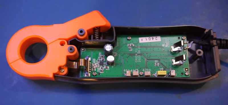
If you physically open a budget current probe, you may find a split magnetic core, a Hall-effect sensor positioned near the core gap, a small printed circuit board, one or more amplifier integrated circuits, trimmer potentiometers, range switches, shielding, wiring to the output connector, and a battery or power input circuit. The mechanical design is often as important as the electronics. A slightly misaligned core can hurt accuracy more than a mediocre op-amp.
Some budget designs are surprisingly tidy. Others look as if the components were placed during a small earthquake. But appearance alone does not prove performance. What matters is how well the core closes, how stable the zero is, how clean the amplifier output remains, and how accurately the probe tracks current across its rated range.
Limitations You Should Respect
Budget current probes are not ideal for measuring tiny microamp sleep currents, very fast nanosecond pulses, high-precision efficiency calculations, or certified safety testing. They are also not a license to casually probe high-energy systems. Clamp-on measurement is convenient, but the circuit may still be dangerous. Use proper insulation, keep fingers away from exposed conductors, and respect voltage ratings.
Another limitation is saturation. If the current is too high, the magnetic core or amplifier can saturate, producing a distorted output. After overload, some probes take time to recover or may need to be zeroed again. Residual magnetism can also shift readings, especially in lower-cost magnetic cores.
Phase shift is another subtle issue. At higher frequencies, the current waveform may appear slightly delayed or distorted. For timing comparisons between voltage and current, this can matter. If you are calculating power from voltage and current waveforms, phase accuracy becomes important, and a budget probe may not be the best tool for the final answer.
How to Decide Whether a Budget Current Probe Is Worth It
A budget current probe is worth buying if your goal is troubleshooting, learning, repair, waveform discovery, and general engineering visibility. It is especially valuable if you often work with motors, switching supplies, LED drivers, battery circuits, amplifiers, or embedded hardware that changes current over time.
Look for a probe with clear output scaling, AC/DC capability if you need DC, enough bandwidth for your application, a usable current range, decent jaw size, a zero function, and a BNC output if you plan to use an oscilloscope. Read the specifications carefully, but also read them skeptically. A large bandwidth number on a cheap probe is less useful if noise, drift, or saturation make real measurements frustrating.
For professional validation, compliance work, or high-frequency power analysis, spend more or use a verified measurement method. For everyday bench work, a budget probe can be one of the most satisfying upgrades you make. It gives current a shape, and once you can see that shape, circuits become much easier to understand.
Field Experiences: Lessons From Living With a Budget Current Probe
The first lesson from using a budget current probe is that it changes how you troubleshoot. Before owning one, many people treat current as a number they measure reluctantly. After owning one, current becomes a waveform you check almost as naturally as voltage. That shift is powerful. A circuit that “doesn’t work” becomes a circuit that draws a suspicious pulse every 200 milliseconds. A motor that “sounds weird” becomes a motor with a startup surge that never settles. A power supply that “gets hot” becomes a supply feeding repeated current spikes into a load that was supposed to be sleeping peacefully.
One practical experience is measuring startup behavior. A bench power supply may show an average current value, but it often misses short inrush events. A budget current probe on an oscilloscope can reveal a sharp peak at power-on, followed by a settling curve. That peak may explain why a connector arcs, why a fuse occasionally opens, or why a small adapter enters protection mode. The waveform does not need laboratory perfection to be useful. Seeing the relative size and timing of the surge can guide better design choices, such as adding soft-start control, increasing input resistance briefly, changing capacitor size, or selecting a more suitable supply.
Another common experience is chasing noise in switching converters. A budget probe may not capture every high-frequency detail, but it can still show whether an inductor current ramp is sane. In a healthy buck converter, you may expect a repeating triangular current waveform. If the probe shows irregular bursts, missing pulses, or a current ramp that suddenly jumps under load, that is a clue. It may point to compensation problems, current-limit behavior, saturation, poor layout, or a load transient the designer forgot to invite to the meeting.
Budget probes also teach humility. You will eventually clamp around both wires of a cable and wonder why the reading is zero. You will forget to zero the probe and spend time diagnosing a fake DC offset. You will use the wrong range and wonder why the waveform looks like a shaved rectangle. You will place the probe near a transformer and discover that magnetic fields do not respect your personal space. These mistakes are not failures; they are tuition payments to the university of practical electronics.
A useful habit is to perform a quick sanity check before trusting the waveform. Clamp around a known load, such as a resistor drawing a predictable current from a bench supply. Confirm the probe reads roughly what Ohm’s law says it should. Then move to the real circuit. This simple step builds confidence and catches embarrassing setup errors. It also helps you learn the probe’s personality: how much it drifts, how noisy it is, how long it needs to warm up, and which range feels most reliable.
Another experience is discovering that current waveforms often explain problems voltage waveforms hide. A voltage rail may look stable while the load current is pulsing aggressively. A motor driver output may show acceptable voltage while the phase current indicates mechanical binding. A microcontroller board may appear to sleep, but the current probe reveals periodic wakeups caused by firmware, radio activity, sensors, or a regulator operating inefficiently at light load. Current is the circuit’s body language. A budget current probe may not speak with perfect grammar, but it understands the gestures.
For repair work, a current probe is especially satisfying. On an unknown device, measuring supply current during startup can quickly separate a dead short from a logic failure, a stalled motor, or a repeated boot loop. In automotive and appliance diagnostics, clamp-style current measurement can reduce disassembly because you can inspect current through accessible wiring. In electronics development, it gives firmware and hardware teams a shared visual reference. Instead of arguing whether a device “probably wakes too often,” everyone can look at the waveform and agree that yes, the device is throwing a tiny current party every few seconds.
The final lesson is that a budget current probe is best treated as a guide, not a judge. Use it to find patterns, compare conditions, locate abnormal behavior, and understand timing. When exact numbers matter, verify with a better instrument, a calibrated shunt, or a known reference. That balanced approach keeps the tool useful without asking it to be something it is not. A budget current probe is not a royal instrument in a velvet-lined case. It is more like a clever shop assistant with slightly messy handwriting: incredibly helpful, occasionally questionable, and worth listening to once you know its quirks.
Conclusion
Looking inside a “budget” current probe reveals a smart blend of magnetic physics, Hall-effect sensing, transformer behavior, amplification, range switching, and mechanical compromise. It is not just a clamp with a cable. It is a compact measurement system trying to convert invisible current into a waveform you can understand.
The best way to appreciate a budget current probe is to use it with realistic expectations. It may not provide premium accuracy, ultra-low noise, or flawless high-frequency response. But it can quickly reveal inrush current, switching behavior, motor load changes, power-supply problems, and hidden current patterns that would otherwise require more invasive measurement methods. For many benches, that is more than enough to justify its place next to the oscilloscope.
In short, a budget current probe is a practical window into current flow. Keep the jaws clean, zero it often, respect its bandwidth, verify important readings, and it will reward you with insights that make troubleshooting faster, smarter, and a lot less mysterious.
Note: This article is written for web publication and synthesizes real electronics measurement principles from reputable test-equipment, engineering, and component-industry knowledge sources.