There is a moment in every engineering project when the spreadsheets have said all they can say. The simulation looks confident, the workshop test produces encouraging numbers, and everyone has consumed enough coffee to begin calling the prototype “basically finished.” Then the hardware meets the real world and politely explains that it has other plans.
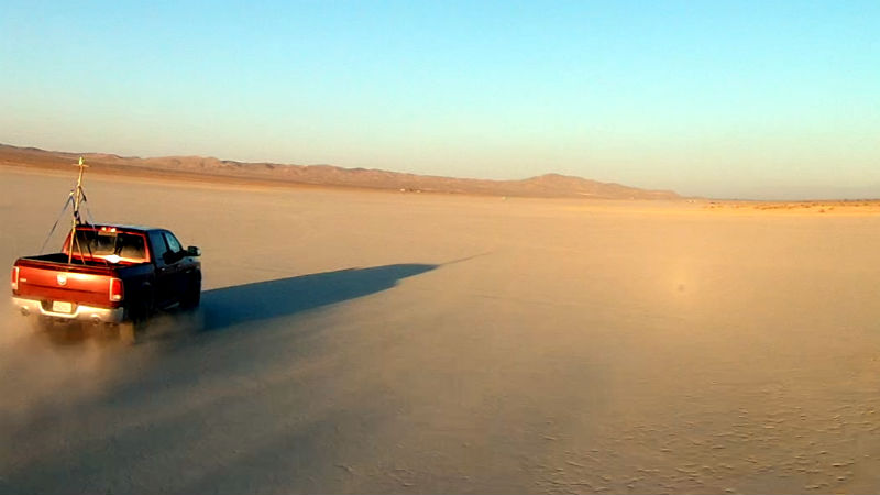
That reality check arrived in spectacularly old-school fashion when quadcopter experimenters took a computer-controlled propeller test rig to California’s El Mirage dry lake bed. Instead of building a conventional wind tunnel, they mounted the equipment on a pickup truck and used the vehicle’s speed to create controlled airflow over a series of high-performance quadcopter propellers.
The resulting lake bed test combined modern data acquisition with a testing location deeply connected to American aerospace history. More importantly, it demonstrated why static thrust figures tell only part of the story. A propeller that performs beautifully while bolted to a bench may behave very differently when air is already rushing through its disk at highway speed.
Why Test Quadcopter Hardware on a Dry Lake Bed?
Dry lake beds have long served as natural laboratories for experimental aircraft. Their broad, flat surfaces provide room for acceleration, emergency recovery, observation, and the occasional engineering decision that turns out to be more exciting than expected.
California’s Mojave Desert is especially famous for this tradition. Rogers Dry Lake helped make Edwards Air Force Base a major flight-test center, supporting experimental aircraft programs and early Space Shuttle landings. El Mirage is smaller and less formal, but it offers many of the same practical attractions: long sightlines, hard-packed terrain, limited obstacles, and enough open space to conduct vehicle-based tests without immediately introducing the apparatus to a mailbox.
For the quadcopter hardware experiment, the dry lake bed effectively became a very long outdoor wind tunnel. Driving a test rig at a measured vehicle speed created forward airflow over the propeller. Repeating the same motor-control routine at different speeds then revealed how the propulsion system responded as the simulated flight condition changed.
Inside the Truck-Mounted Quadcopter Test Rig
The experiment was conducted by James and Tyler of Propwashed, who assembled a mobile propulsion laboratory in the bed of a pickup. At the center of the setup was an RCbenchmark Series 1520 thrust stand mounted on a raised structure behind the cab.
The stand supported an EFAW 2407 2500Kv brushless motor and allowed the team to collect several important measurements at once. Depending on the configured sensors, this class of equipment can monitor thrust, rotational speed, current, voltage, and electrical power. Instead of relying on a pilot’s impression that one propeller felt “a little more spicy,” the system converted each run into data that could be graphed and compared.
A Script Made Every Run More Consistent
A computer-controlled test sequence gradually increased throttle from zero to 70 percent over approximately 30 seconds. The system then held the final throttle setting for five seconds before completing the run.
Automating the throttle ramp was an important detail. Human operators are not especially good at moving a control through exactly the same positions at exactly the same rate dozens of times. We are, however, excellent at insisting that our thumb was perfectly consistent. A script removes that argument and improves repeatability.
The first measurements were collected while the truck was stationary. The sequence was then repeated as the vehicle traveled at progressively higher speeds, eventually reaching roughly 90 mph. Fifteen different propellers were evaluated using the same basic procedure.
Why the Rig Used Separate Batteries
The team considered powering the equipment from the truck’s electrical system but ultimately used Turnigy 6000mAh 4S lithium-polymer battery packs. This simplified the installation and kept the propulsion circuit separate from the vehicle.
A dedicated battery also made the electrical arrangement more representative of an actual quadcopter. The battery, electronic speed controller, motor, and propeller could operate as a self-contained propulsion system rather than borrowing power from an automotive alternator and wiring network.
That choice did introduce another variable: battery voltage changes under load and declines during use. Careful testing therefore requires monitoring pack voltage, temperature, state of charge, and recovery time between runs. Otherwise, the last propeller tested may appear weaker simply because the battery has already spent the afternoon doing electrical cardio.
Static Thrust Is Only the Beginning
Most hobby propulsion comparisons begin with a static thrust test. The motor and propeller remain fixed while the stand measures force at different throttle settings. These tests are convenient, repeatable, and useful for estimating whether a quadcopter has enough thrust to lift its intended weight.
However, a static test represents an advance ratio of zero because the propeller has no forward speed through the surrounding air. That condition resembles hovering, but it does not represent rapid forward flight.
As a quadcopter accelerates, incoming air changes the angle at which the relative airflow meets each blade. Thrust, torque, motor load, and efficiency may all change. Two propellers that produce nearly identical static thrust can separate dramatically once they are exposed to moving air.
What Advance Ratio Tells Engineers
Propeller engineers commonly describe forward-flight conditions using advance ratio. In simplified terms, it compares forward airspeed with the propeller’s rotational speed and diameter. A higher vehicle speed, lower rotational speed, or smaller propeller diameter increases the advance ratio.
This is why professional propeller databases include measurements across a range of airspeeds and RPM values rather than publishing only one impressive static number. The useful question is not merely, “How much thrust does this propeller make?” It is, “How much thrust, torque, and efficiency does it deliver at the speed and rotational load my aircraft will actually encounter?”
What the Lake Bed Results Revealed
The truck-mounted tests illustrated a broad inverse relationship between forward airspeed and generated thrust under the tested conditions. As airflow through the propeller increased, the measured thrust generally fell.
The decline was not identical for every propeller. Blade count, pitch, geometry, stiffness, and aerodynamic design affected how quickly performance changed. That variation was the most valuable part of the experiment because it showed that propeller choice cannot be reduced to diameter alone.
Lower-Pitch, Two-Blade Props Performed Well Overall
Across the comparison, lower-pitch propellers with fewer blades tended to provide strong all-around results. This broadly matched the practical experience already circulating among high-performance quadcopter builders.
A two-blade propeller usually has less blade area and may require less torque than a comparable three- or four-blade design. That can reduce current demand and help a motor maintain RPM. Lower pitch can also be easier for the motor to handle, particularly during rapid throttle changes.
That does not mean a low-pitch two-blade propeller wins every competition. Additional blades can provide more grip, smoother response, compact thrust capability, or desirable handling characteristics. Higher-pitch designs may retain useful thrust at greater forward speeds. Several props in the lake bed test stood out at the faster test points even though they were not the strongest overall performers.
The correct choice depends on the mission. A freestyle quad, racing quad, camera platform, long-range aircraft, and heavy-lift machine do not ask the propulsion system to solve the same problem.
The Motor, Propeller, ESC, and Battery Form One System
Propellers are often discussed as interchangeable accessories, but they influence nearly every part of a quadcopter’s powertrain. Increasing diameter, pitch, or blade count generally increases the torque demanded from the motor. That can raise current through the electronic speed controller and battery.
If the motor cannot maintain the requested speed, RPM falls. If the ESC is undersized or poorly cooled, it may overheat. If the battery has excessive internal resistance, its voltage can sag under load. The flight controller then attempts to stabilize an aircraft whose available thrust is changing underneath it.
A propulsion setup should therefore be evaluated as a complete system:
- The propeller converts shaft power into aerodynamic thrust.
- The motor supplies torque and rotational speed.
- The ESC commutates the motor and controls its power.
- The battery supplies voltage and current.
- The frame and flight controller manage vibration and vehicle response.
Optimizing only one component can produce misleading results. A propeller with excellent theoretical performance is not an improvement if it pushes the motor beyond its efficient operating range or turns the battery into an expensive hand warmer.
Why the Pickup Test Was Clever but Not Perfect
The El Mirage setup was an inventive and practical way to collect dynamic propeller data without constructing a full wind tunnel. It also had limitations that matter when interpreting the graphs.
Vehicle Wake and Flow Quality
Air behind a moving pickup is not perfectly uniform. The cab, bed, mounting tower, and surrounding equipment create turbulence and local pressure changes. A propeller sitting in that disturbed flow may experience a different airspeed from the vehicle’s indicated road speed.
Positioning the stand high above the bed helps, but it does not eliminate every wake effect. A calibrated airspeed sensor located near the propeller would provide a better measurement than vehicle speed alone.
Natural Wind Changes the Effective Airspeed
A headwind adds to the airflow generated by the truck, while a tailwind subtracts from it. Crosswinds can introduce angled flow across the propeller disk. Running reciprocal passes, recording local wind, and repeating test points can help identify these effects.
Temperature and Air Density Matter
Hot desert air is less dense than cooler air at the same pressure. Lower density reduces the mass of air acted upon by the propeller, affecting measured thrust. Battery and motor temperatures also change electrical resistance and performance.
Meaningful comparisons should record ambient temperature, pressure, humidity, battery temperature, motor temperature, and test order. Without those details, small differences between propellers may reflect the afternoon weather rather than superior blade design.
Instrumentation Must Be Verified
Load cells require calibration, RPM sensors need a clean signal, and current sensors can drift. The mounting structure must also be stiff enough to prevent vibration or flex from corrupting the measurements.
Good experimental practice includes zeroing the stand before each run, checking fasteners, inspecting blades, repeating selected tests, and using a known reference configuration to confirm that the system still produces expected values.
From Lake Beds to Modern Drone Development
The pickup experiment sits between two familiar testing approaches. It is more realistic than a stationary bench test but less controlled than a laboratory wind tunnel. That middle ground is valuable because real engineering rarely depends on one method.
Modern quadcopter development may combine computer simulation, static thrust testing, wind-tunnel data, hardware-in-the-loop evaluation, tethered testing, onboard telemetry, flight-controller logs, and carefully planned outdoor flights.
Simulation can screen many designs quickly. A thrust stand can identify electrical and mechanical problems without risking an entire aircraft. Dynamic airflow testing reveals speed-dependent behavior. Flight testing then shows how the complete vehicle responds to prop wash, vibration, control inputs, gusts, and rapidly changing attitudes.
The methods support one another. A simulation without physical validation may contain incorrect assumptions. A physical test without instrumentation may produce only a dramatic video. The best development programs use both modeling and measurement, with enough skepticism to keep either one from becoming the office fortune-teller.
Safety and Legal Planning for Similar Tests
A spinning quadcopter propeller can cause severe injury, especially when attached to a high-Kv motor and a high-discharge battery. A vehicle-mounted test adds road speed, dust, vibration, and moving equipment to the hazard list.
A safe test plan should include a clearly marked exclusion zone, remote motor shutdown, secure structural mounting, protective barriers where practical, eye protection, fire-resistant battery handling equipment, and a spotter who is not simultaneously operating a laptop or driving.
Propellers should be inspected before every run. Even a minor crack, damaged hub, loose adapter, or incorrectly tightened fastener can become dangerous at high RPM. The test sequence should remain below the manufacturer’s rotational and power limits.
Public land does not mean rule-free land. Vehicle use, filming, commercial activity, temporary structures, and drone operations may require permission depending on the location and scope of the project. If an aircraft is flown, FAA requirements concerning registration, airspace, visual line of sight, altitude, Remote ID, and recreational or commercial status may apply.
El Mirage is also an active off-highway vehicle recreation area. Anyone planning a modern test there should verify current BLM conditions, closures, access rules, and permits rather than assuming that an eight-year-old video functions as permanent authorization.
Experience-Based Lessons for Conducting a Quadcopter Lake Bed Test
A field test often teaches lessons that are invisible during workshop preparation. The first is that logistics can dominate engineering. A perfectly calibrated thrust stand is not useful if a connector is missing, the laptop overheats, the battery charger lacks sufficient power, or wind-driven dust turns every exposed bearing into a miniature geology project.
Prepare the Test Matrix Before Leaving Home
Each propeller should receive an identification code, planned test speed, throttle sequence, battery assignment, and run order. Randomizing or rotating the order can reduce bias caused by rising temperatures and declining battery performance. Recording the plan in advance also prevents the team from inventing procedures beside the truck after discovering that nobody remembers which propeller was tested third.
Run a Low-Power Shakedown First
The first field run should confirm sensor operation, motor direction, emergency shutdown, data recording, and structural stability at low power. Jumping directly to a 90-mph, high-throttle run is an efficient way to discover five problems simultaneously and learn almost nothing about which one caused the failure.
Keep Batteries Comparable
Matching the state of charge matters because voltage affects motor speed and available power. Packs should begin within a narrow voltage range and receive adequate cooling between runs. Logging voltage and current allows later analysis to distinguish aerodynamic changes from electrical sag.
A practical approach is to rotate several similar batteries, label them clearly, and record which pack powered each run. Any swollen, damaged, unusually warm, or imbalanced battery should be removed from service immediately.
Repeat More Than the Most Exciting Result
An unexpected high-speed winner deserves another run, not an immediate trophy. Repeating measurements helps determine whether the result came from the propeller, a gust, a sensor error, or a particularly enthusiastic bump in the lake bed.
At least one reference propeller should be retested periodically throughout the day. If its measurements drift significantly, the team has evidence that conditions or instrumentation have changed.
Record Context Alongside Numbers
Useful field notes include wind direction, ambient temperature, battery temperature, motor temperature, vehicle heading, surface condition, vibration, unusual noises, and interruptions. A data file may say that thrust suddenly dropped, while a handwritten note explains that the truck crossed a rut and the entire test tower shook like a shopping cart with one rebellious wheel.
Inspect Hardware After Every Run
Fasteners can loosen, propeller hubs can develop stress marks, wires can rub against the mount, and dust can enter connectors. A brief physical inspection between runs is cheaper than replacing a motor, thrust stand, rear window, and several pieces of personal confidence.
After testing, photographs of the setup, configuration files, calibration records, raw data, processed graphs, and observations should be stored together. That documentation transforms an entertaining experiment into a reproducible engineering study that other builders can examine, question, and improve.
Conclusion
The classic lake bed test proved that serious quadcopter research does not always require a giant laboratory. A computer-controlled thrust stand, a carefully designed script, an open stretch of desert, and one very committed pickup truck can reveal how propulsion hardware behaves under realistic moving-air conditions.
The experiment confirmed a central lesson of aircraft development: static performance is not flight performance. Propeller thrust changes with airspeed, RPM, blade geometry, electrical load, and environmental conditions. Lower-pitch, low-blade-count props performed strongly across much of this particular test, while other designs showed advantages at higher speeds.
More broadly, the project demonstrated the value of replacing assumptions with measurements. Simulations, manufacturer specifications, and workshop tests are useful starting points, but hardware eventually deserves a proper encounter with the atmosphere. Preferably somewhere flat, empty, legal, and far away from the neighbor’s new car.